Get in Touch with Engelhardt

Vulcanization vs Adhesive Bonding vs Mechanical Fastening: Choosing a Rubber-to-Metal Joint

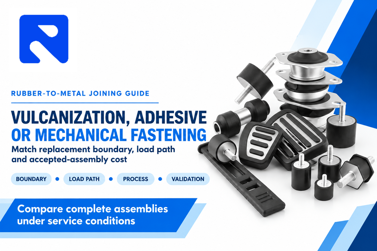
Use vulcanization bonding for an integrated molded assembly. Use adhesive bonding for separately molded components. Use mechanical fastening when the interface requires access or replacement. In all these cases, the service condition and the environment must be satisfied. The choice of any of these methods means a lower cost of joining, which, however, is of interest only after the assembly has performed its function.
Of vulcanization, adhesive bonding and mechanical fastening, the labels overlap. In-mold rubber-to-metal bonding usually takes a primer and adhesive route, and some pieces of bonding may require heat. This work compares those routes and delineates their boundaries. Engelhardt’s rubber-to-metal bonding services page covers the manufacturing routes.
Quick selection inputs
- Rubber condition: uncured compound or an already molded part.
- Replacement unit: rubber alone, a bonded insert, or the complete assembly.
- Duty: force direction, movement, vibration and exposure.
- Production basis: accepted quantity, fixture occupancy and inspection method.
Vulcanization vs Adhesive Bonding vs Mechanical Fastening at a Glance
Vulcanization bonding joins rubber to an insert. Post-cure adhesive bonding joins separately molded components. Mechanical fastening connects pieces through hardware or interlocking features. These are purchasing criteria, but don’t delineate three mutually exclusive chemistries. A bonded rubber mount can itself be bolted into a machine.
| Decision criterion | In-mold vulcanization bonding | Post-cure adhesive bonding | Mechanical retention |
|---|---|---|---|
| Starting rubber | Uncured compound placed with the insert | Previously cured rubber component | Finished rubber component with retention features |
| Main interface | Bond formed during molding and cure | Prepared surfaces joined through adhesive | Clamped, captured or interlocked surfaces |
| Process commitment | Mold, insert location and cure cycle | Application, alignment and curing fixture | Hardware access and assembly sequence |
| Heat constraint | Insert and finish must tolerate the molding cycle | Ambient or heated route, according to the system | No adhesive cure in a purely mechanical joint |
| Load transfer | Through rubber and bonded interface | Through rubber, adhesive and substrate interfaces | Through contact, bearing or retained compression |
| Replacement planning | Often defined around a bonded subassembly | Define whether the backing is reused or replaced | Threaded access differs from permanent riveting |
| Geometry constraint | Mold access and rubber flow around inserts | Bond area, edge loading and adhesive thickness | Holes, edge distances and rubber deformation |
| Production control | Insert preparation and molding consistency | Surface preparation, application and cure state | Hardware, seating and retention consistency |
| Cost exposure | Tooling allocation and accepted output | Preparation labor and fixture occupancy | Part count, assembly labor and service access |
What is adhesive bonding?
Adhesive bonding uses an adhesive layer between two substrates to develop adhesion to each of them and strength in the layer. In the case of rubber-to-metal parts, the adhesion can happen in the rubber mold. Calling a route adhesive bonding, therefore, doesn’t answer a purchasing question: which of the components arrive finished, and at what stage does the joining take place?
For example, Parker’s 2025 post-vulcanization bonding guide gives a conventional Chemlok oven example of 30–60 minutes at 137–150 °C with rubber compression. The epoxy and urethane section also describes systems that cure at room temperature. These are different processes for already cured rubber, so “post-vulcanization” doesn’t mean “cold bonding.”
Joining materials like metal, plastic and composite panels can involve welding or structural adhesives. Rubber can’t be joined to a metal insert by a conventional metal weld; a proposal to replace welding on the backing bracket still leaves the rubber interface to be designed. Define how to create a joint at each interface, and keep those two joints separate in the drawing.
Start with the Replacement Boundary
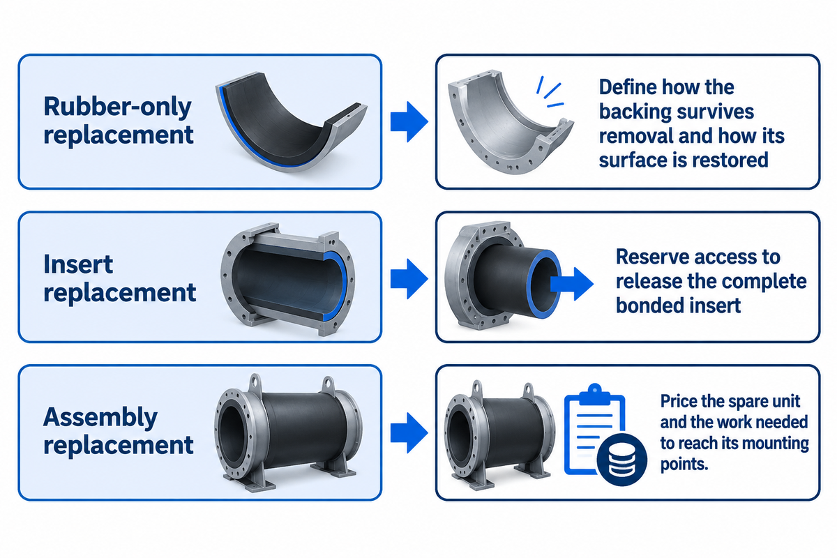
Choose the item maintenance must remove before choosing how to fasten it. Replacing a bonded pad and its backing plate is a different task from peeling the pad off and reusing that plate. Mechanical fasteners offer useful access only when the hardware, surrounding clearance and retained part are designed for disassembly.
The SME’s fastening guide (2009) distinguishes threaded assemblies used for later removal from permanent rivets. Mechanical fasteners include bolts and screws, but they don’t create the same service operation. So, “Using mechanical fasteners” is too broad to be used as a maintenance specification.
- Rubber-only replacement: define how the backing survives removal and how its surface is restored.
- Insert replacement: reserve access to release the complete bonded insert.
- Assembly replacement: price the spare unit and the work needed to reach its mounting points.
Design example: a replaceable wear pad
To replace a worn rubber pad during a scheduled stop without removing adhesive from a large machine frame, a maintenance team is considering one of two options. In the first option, a bonded pad is mounted on a removable metal carrier. In the second option, a rubber pad is restrained by a removable retaining plate. The first option keeps bonding work off the machine frame. The second option changes how the rubber is restrained.
The engineer has drawn the pad in the working condition, before locating hardware. A projecting screw head could contact the moving part, and inaccessible nuts could erase the expected downtime saving. The purchase specification identifies the type of replaceable carrier or retaining plate, the access opening, and the required working clearance. Bonding and/or bolting can serve different interfaces in the same assembly.
Compare the Load Path, Not a Strength Label
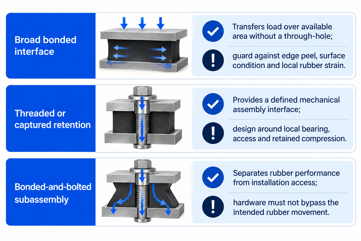
For a mechanical fasteners vs adhesives comparison, test complete joints under the same load direction, movement and environmental conditions. A peel-strength test and a bolted joint load-bearing test, however, may not be compared. This is because they define failure based on different kinds of geometries. For repeated loading, Edge-peel and bond durability tests, and retained contact and movement may be included in the adhesive test plan, while for friction, Adhesive joints may be used.
NASA’s adhesive-joint design guidance treats shear and peel as different design concerns. It notes that broad-area stress distribution is an advantage of using adhesives, but an eccentric load can peel a corner of a sheet, leaving the remainder unloaded. For existing failures, the separate bond failure diagnosis guide should be consulted.
| Joint feature | Useful advantage | Limitation to design around |
|---|---|---|
| Broad bonded interface | Transfers load over available area without a through-hole | Edge peel, surface condition and local rubber strain |
| Threaded or captured retention | Provides a defined mechanical assembly interface | Local bearing, access and retained compression |
| Bonded-and-bolted subassembly | Separates rubber performance from installation access | Hardware must not bypass the intended rubber movement |
What are the disadvantages of using adhesives?
Adhesives provide surface condition control, place limits on the type and thickness of the materials to be joined, and a wait time before the joint can be loaded. Hidden interfaces can complicate inspection, and peeling or recovering a bonded part increases maintenance burden. For a rubber joint, these disadvantages become design inputs: provide enough usable bond area, control edge geometry, and instruct production on how to detect unacceptable joints.
High bond strength also discusses very little on vibration isolation. A 2023 SAE mount study states that competition exists to manage low stiffness for isolation and to control lateral displacement for large input motions. Specify stiffness, displacement, and vibration response; impact resistance or survival alone doesn’t ensure isolation.
Match the Rubber, Metal and Service Environment
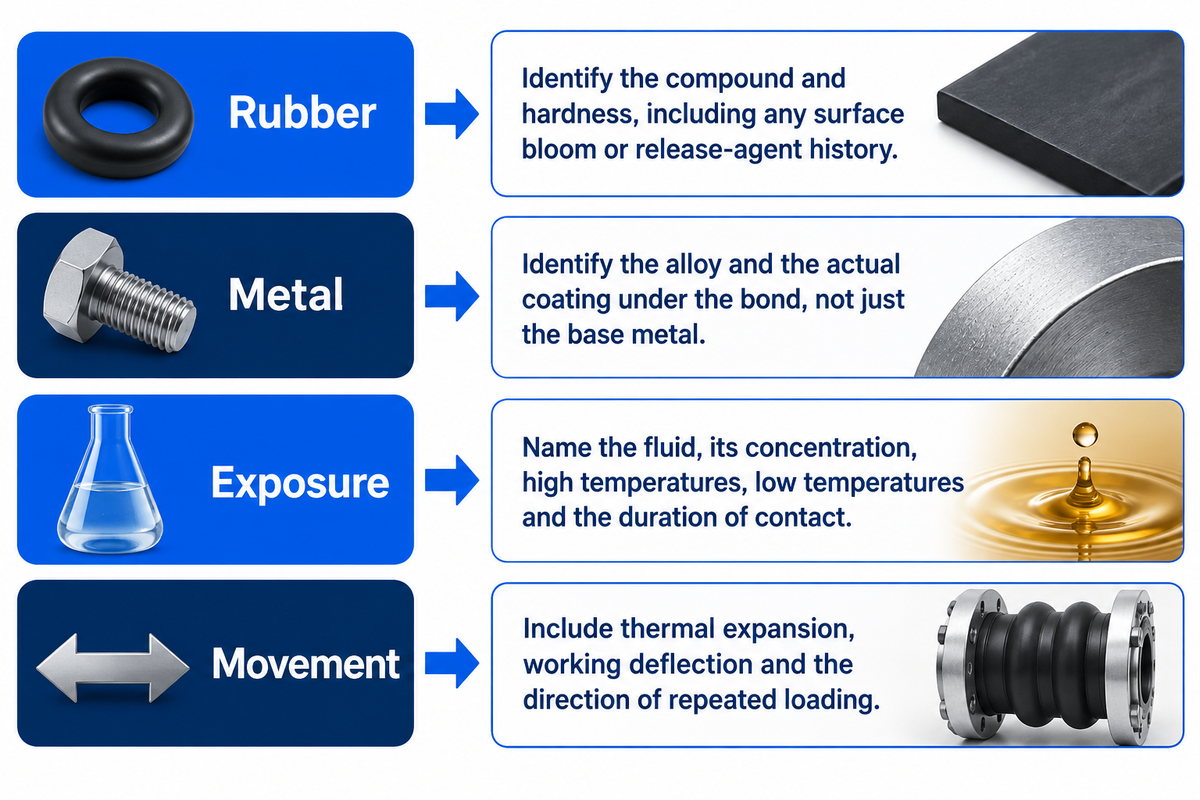
Exact rubber compounds and metal finishes determine the candidate routes. Family labels like EPDM and NBR are a starting point. Additives and the surface condition of the components and the finished interface are also critical. Evaluate the joined parts after the combination of fluid, temperature and deformation they will experience.
- Rubber: identify the compound and hardness, including any surface bloom or release-agent history.
- Metal: identify the alloy and the actual coating under the bond, not just the base metal.
- Exposure: name the fluid, its concentration, high temperatures, low temperatures and the duration of contact.
- Movement: include thermal expansion, working deflection and the direction of repeated loading.
Parker’s Principles of elastomer bonding covers the effects of contamination and processing on the interface. Select the right adhesive from epoxy, acrylic or urethane systems based on the compound, surface condition and processing. The EPDM and NBR comparison helps in arriving at a system before selecting the joining method.
Design example: a coated bracket with a heat limit
A design engineer receives a finished coated bracket and a molded rubber strip. The coating can’t go through the proposed heated bonding cycle. The engineer considers an ambient cure adhesive solution and a captured strip as two options.
For the adhesive route, the coating is an interface in the load path. A test on bare metal, without the coating, may miss it. The team assesses if the change of the retainer permits movement. The RFQ lists the coating and the allowed part temperature, and asks each supplier to price the compatible assembly. A cheap joining operation loses its advantage if it requires refinishing the bracket.
The chosen system may become brittle at the lowest service temperature or lose required retention after fluid exposure. A sealant used to close a gap and an adhesive carrying structural load have different jobs, even if a formulation can perform both. Corrosion protection must cover the entire interface, including exposed edges and hardware.
Account for Preparation, Cure and Assembly Bottlenecks
Measure the time a route takes people, fixtures and equipment. Don’t just measure the time spent in applying adhesive and tightening hardware. Preparation, drying, cure times and inspection can determine output. Adhesive handling strength is the release point for the next specified operation; it’s distinct from the final cure state.
| Stage | What can hold output back? | Measurement to request |
|---|---|---|
| Surface preparation | Cleaning, coating variation or a contaminant on stored inserts | Prepared parts available per shift; reject reason |
| Application | Mixing, dispensing, coverage and work-life limits | Actual application time and discarded material |
| Alignment | Parts moving before the joint holds itself | Occupied fixtures and time to permitted handling |
| Heating or curing | Loading, warm-up, holding and unloading | Complete equipment occupancy per batch |
| Mechanical assembly | Hardware presentation, access and seating checks | Labor per assembly and first-pass acceptance |
| Inspection | Destructive sampling, screening or delayed results | Release time, sample consumption and disposition |
3M’s structural-adhesive processing discussion separates work life, time to handling strength and final cure. Many adhesives need a fixture while they develop holding capability; adhesives often create a queue that’s invisible in a short application-time estimate. Adhesives can also require mixing or controlled dispensing before the parts meet.
Adhesives can be applied manually or with dispensing equipment, but the application method must control coverage and bondline thickness. Using structural adhesives therefore changes the assembly processes beyond the adhesive station. Replace vague instructions such as “sand the metal” with the agreed preparation procedure. Put proper surface preparation and the allowed release condition into the quotation; detailed rubber-to-metal preparation and adhesive assembly steps belong in the process plan.
Compare Cost per Accepted Assembly
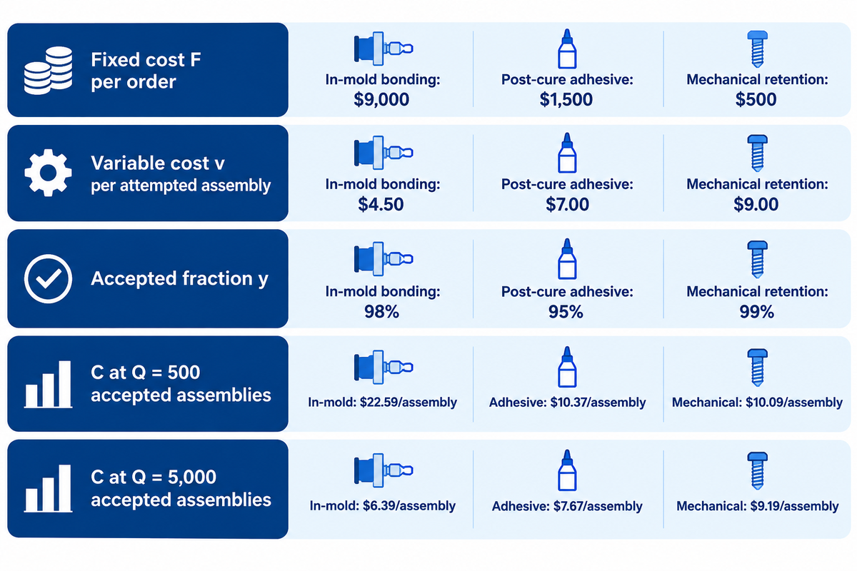
Compare the same delivered quantity after each candidate meets the required service performance and production acceptance plan. Distinguish fixed costs from variable costs per attempted assembly, and consider the observed accepted fraction. An insensitive inspection method doesn’t reveal a true manufacturing advantage from a high pass rate.
Lawrence Berkeley National Laboratory’s manufacturing cost model separates cost categories and relates expenses to output. A simpler worksheet below performs a similar calculation at the order-level: C = F / Q + v / y, where F is fixed setup/tooling cost, Q is accepted assemblies, v is variable cost per attempt, and y is the accepted fraction.
Illustrative assumptions, not supplier prices: all routes cover the same materials, inspection and packaging scope. The example excludes rework recovery, scrap disposal, freight, financing and field service; it assumes the accepted fraction stays constant at each order size. Those excluded costs need separate quote lines.
| Input or calculated result | In-mold bonding | Post-cure adhesive | Mechanical retention |
|---|---|---|---|
| Fixed cost F per order | $9,000 | $1,500 | $500 |
| Variable cost v per attempted assembly | $4.50 | $7.00 | $9.00 |
| Accepted fraction y | 98% | 95% | 99% |
| C at Q = 500 accepted assemblies | $22.59/assembly | $10.37/assembly | $10.09/assembly |
| C at Q = 5,000 accepted assemblies | $6.39/assembly | $7.67/assembly | $9.19/assembly |
For the in-mold route at the larger order, $9,000 / 5,000 + $4.50 / 0.98 = $6.39 per accepted assembly after rounding. If its assumed acceptance falls to 75%, the same calculation becomes $7.80, above the adhesive example. Depending on which characteristics of product design or rejection performance are changed, a different route to manufacture could be chosen based on volume produced without affecting joining method’s quoted cycle time.
Trial and larger orders can favor different routes because fixed setup/tooling cost is spread over different accepted quantities. For example, Procurement should request both quantities, and the plant manager should check if the assumed acceptance is supported by the production records. The quality lead should first confirm that the acceptance method used detects the relevant service defects.
If a supplier recovers rejected inserts, ask for the labor, usable fraction, and repeat-inspection cost instead of simply raising y. ASQ’s cost-of-quality framework separates appraisal, scrap, rework and customer failure costs. Keep these visible. The separate custom rubber molding cost guide covers tooling and molding cost drivers in more detail.
Test the Complete Joint under the Same Conditions
Mount tests should cover the response of the assembly to movement and vibration, and its retention, while gasket tests should cover the sealing behavior of the assembly after exposure. Compare routes against a common service requirement using tests appropriate to each route and failure mechanism. Distinguish design qualification from routine production acceptance.
| Method in D429-14(2023) | Scope stated by ASTM | Comparison implication |
|---|---|---|
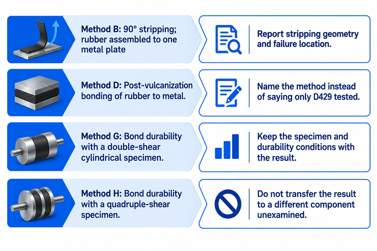
| B | 90° stripping; rubber assembled to one metal plate | Report stripping geometry and failure location |
| D | Post-vulcanization bonding of rubber to metal | Name the method instead of saying only “D429 tested” |
| G | Bond durability of rubber-to-metal bonded components with a double-shear cylindrical specimen | Keep the specimen and durability conditions with the result |
| H | Bond durability of rubber-to-metal bonded components with a quadruple-shear specimen | Do not transfer the result to a different component unexamined |
ASTM D429 supports laboratory adhesion comparisons and production specimen examination. There are several factors that influence a component’s duty rating including the actual geometry, environment, and load history. State the failure criterion, and record if separation occurs at the metal, adhesive, coating, or rubber.
Engineering note: retained compression
For rubber held at a fixed deformation, ASTM D6147-97(2026) describes force decay with time. Record the compression dimension and its tolerance on the drawing, then specify temperature, duration, initial stress and mechanical history for the force-decay assessment. This connects the clamped geometry to a measurable retention requirement.
“the force necessary to maintain that strain is not constant but decreases with time”
The same standard states that extrapolation of force decay curves beyond the test duration and the use of elevated temperatures to predict performances at lower temperatures are incorrect. For applications that require long retention, agree the relevant exposure schedule before determining the test duration.
Production screening relies on its own evidence. A 1986 rubber-steel study hosted by NASA correlated acoustic measurements with destructive peel results; a 1994 FAA weak-bond study showed that inspection criteria affected false rejection in aerospace bonding research. Ask how the proposed screen correlates with relevant defects, then track escapes and rejects separately.
Do
- Test the actual finish and compound.
- Compare the required working movement.
- Record exposure and failure location.
Don’t
- Do not rank routes by unrelated shear figures.
- Do not treat a clean-looking interface as a strength test.
- Do not equate production pass rate with field reliability.
Ask for lot ID and the agreed acceptance records with the samples. The bonding documentation and traceability guide address the purchasing records behind that handoff.
Choose a Route with the 3-Change Joint Selector

Change the shortlist if the allowed manufacturing process or the accepted-output economics changes. Keep a route only if it meets the service requirement. This sequence prevents choosing adhesives to replace mechanical fasteners solely to remove holes, or choosing hardware solely to avoid an adhesive cure.
- Change the replacement boundary. Decide whether maintenance removes rubber, an insert or the whole assembly.
- Change the process constraints. Screen heat, surface preparation, fixture access and coating compatibility.
- Change the accepted-output economics. Recalculate the same order quantity with credible acceptance and service assumptions.
| Situation | Route to investigate | Condition that changes the decision |
|---|---|---|
| New molded insert with a stable design | In-mold bonding | Insert or coating cannot tolerate the cure cycle |
| Already cured rubber and a finished backing | Post-cure adhesive | Surface or fixture requirements cannot be controlled |
| Wear element removed during service | Removable carrier or captured part | Hardware is inaccessible in the installed position |
| Rubber needed for isolation | Bonded or captured mount geometry | Retention creates an unwanted rigid load path |
| Thin metal face where holes are undesirable | Broad-area adhesive joint | Edge peel or coating adhesion governs failure |
| Repeated access to the assembly | Threaded mounting interface | Fasteners are used inside the moving rubber zone |
| Existing metal core must be reused | Recoverable bonding or removable retention | Removal damages the core or its required finish |
| Heat-sensitive assembled parts | Compatible ambient-cure system or mechanical retention | Chemical compatibility or local deformation fails |
| Large repeat order | All service-qualified routes, costed at that quantity | Yield, tooling life or inspection burden changes |
A proposal to use adhesives instead of hardware should state which joint changes and which function stays the same. Review the fastening techniques at that interface, including hybrid joining where bonding and point fasteners serve complementary roles. A high-performance assembly still needs a defined load path; adding both methods doesn’t automatically split the load equally.
What to Include in a Joining-Method RFQ
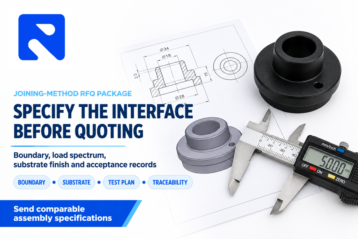
Have all suppliers bid on the same drawing, service duty and acceptance requirements and provide route-specific process and cost assumptions. Procurement proposals can only be compared when the scope of the supplied work is the same as the replacement work unit. The quality lead should define the acceptance criteria and the process window, while the production unit determines the allowed process.
These criteria should be specified in the RFQ and the related drawings should be provided. State your application’s measured load, temperature and tolerance.
| Parameter | Recommended range | Why it matters | How to verify |
|---|---|---|---|
| Load and movement | Application minimum/maximum in N and mm | Defines load path and retention | Load cases and assembly test |
| Service exposure | Measured °C range; fluid and contact duration in h | Screens compound and interface | Aged-part test plan |
| Geometry and finish | Drawing dimensions and tolerances in mm | Controls compression, fit and bondline | Inspection report and finish specification |
| Replacement boundary | Rubber, insert or complete assembly | Defines spare and access work | Installed removal demonstration |
| Production release | Permitted handling load in N and release time in min | Sets fixture occupancy | Process trial and release criterion |
| Order and acceptance | Accepted pieces per order; observed acceptance in % | Normalizes production cost | Qualified inspection and lot records |
| Quoted scope | Fixed cost per order and variable cost per attempt | Separates tooling, rework and service | Itemized quotation |
Engelhardt describes manufacturing services spanning from rubber, silicone to plastic, tooling and hardware. Use this component view while requesting a rubber-to-metal assembly assessment, and send the rubber specification, metal finish and working load along with the intended replacement unit.
Key takeaway
Choose the joint around its service function and replacement boundary, then compare the cost of producing the same accepted quantity. Route names alone do not determine strength, removability or value.
Frequently Asked Questions
Are adhesives stronger in shear or tension?
Neither shear nor tension is always stronger. The higher measured strength depends on the adhesive formulation, specimen geometry and test conditions. Both are useful loading modes for structural adhesives; peel and cleavage concentrate load at an edge. For a rubber-to-metal part, start with the service force direction and choose a test specimen that represents that loading.
When can an adhesive-bonded part leave its fixture?
Release it when the selected adhesive has reached the handling strength required for the next operation. That may occur before final cure, so fixture release doesn’t automatically permit full service loading. Use the product’s cure schedule at the actual part temperature, and include any load introduced during transport, trimming or assembly.
How does thermal expansion affect a rubber-to-metal joint?
Different materials can change dimensions by different amounts as temperature changes, adding deformation to the joint. The effect depends on geometry, restraint and material behavior. Include the working temperature cycle in testing of bonded joints, especially where a thin adhesive layer or a constrained rubber section must accommodate movement between dissimilar materials.
Can you combine adhesive bonding and mechanical fastening?
Yes. Adhesive bonding and mechanical fasteners can serve different interfaces or form a designed hybrid joint. Define each element’s role and verify the load sharing.
Does rubber tearing prove the joint will last?
No. Rubber tearing identifies where a particular test specimen failed; it doesn’t establish the assembly’s service life. Parker’s elastomer-bonding guidance distinguishes thin or spotty rubber residue from heavier cohesive rubber failure. Record the amount and location of residue together with load, exposure and test method. A sample that tears during an initial pull test still needs the relevant aging and cyclic tests, including checks on its required movement or sealing function.
Is vulcanization bonding always cheaper at high volume?
No. Higher output spreads fixed tooling cost, but acceptance, insert preparation, cycle occupancy and inspection still affect the result. Use the accepted-assembly worksheet with quoted inputs; high volume alone can’t compensate for an unsuitable process or expensive rejects.
How will the adhesive be applied?
The application method follows the adhesive system and part geometry: it may use brushing, spraying or controlled dispensing. A two-part system also needs the specified mixing method. Ask the supplier how it controls coverage, thickness and work life before the final bond develops. Surface energy and any solvent or contamination affect wetting, so the trial should use the actual finished parts. Adhesives also need an application process that remains repeatable over the proposed production run.
Define the joint before requesting a price
Send the assembly drawing, rubber compound, metal finish and service conditions to Engelhardt. Include the replacement unit and accepted order quantity so the joining proposal and quotation address the same task.
Request an assembly reviewReferences & Sources
- SME — Fastening & Assembly.
- National Aeronautics and Space Administration — Simplified procedures for designing adhesively bonded composite joints (1989).
- SAE International — Experimental Validation of Vibration Isolation in Quasi-Zero Stiffness Mount Concept (2023).
- Lawrence Berkeley National Laboratory — Manufacturing Cost Levelization Model: A User’s Guide (2015).
- American Society for Quality — Cost of Quality.
- ASTM International — D429-14(2023), Rubber Property: Adhesion to Rigid Substrates.
- ASTM International — D6147-97(2026), Force Decay in Compression.
- NASA Technical Reports Server — Nondestructive evaluation of adhesive bond strength using the stress wave factor technique (1986).
- Federal Aviation Administration — Nondestructive Inspection of Reduced Strength Bonds, DOT/FAA/CT-93/42 (1994).
- TWI — What is hybrid joining?.
Trending now