Get in Touch with Engelhardt

Rubber Compression Molding E×plained: A Process, Material & Tolerance Reference for Design Engineers
The original commercial elastomer-shaping method in the world: rubber compression molding, which is still the most economical shape forming option for the FKM, EPDM and silicone large-volume low-cavity-count components. The following brief introduction includes the process chemistry, the tolerance possibilities (under ISO 3302-1), the defect root causes that none of our competitors blogs mention (i.e. that site has no clue), the ASTM D2000 to choose rubber material and the volume principle to select the reason for going the way of transfer/injection molding in large quantities.
Quick Specs: Rubber Compression Molding
- Process Type: Thermoset elastomer (TSE) form shaping using a hard mold. Resin preformed into a shape and loaded into a heated closed mold — pressure applied to cure.
- Typical mold temperature: 150–200 °C (302–392 °F)
- Typical clamp pressure: 2,000–4,000 psi (14–28 MPa)
- Cycle time: 3-15min per cure (rubber injection molding is in the order of 1-4min)
- Costenveloppe tooling: ~$2,000-$15,000 per drukgietvorm (bedrijfswinkel range, vormafhankelijk)
- Range of practical sizes of part: 0.024in to 30in (0.6mm – 762mm), for Apple Rubber.
- Best tolerance class: ISO 3302-1 Class M2–M3 (±0.15 to ±0.80 mm depending on nominal dimension)
- Elastómeros más comunes: EPDM, NBR, FKM (Viton), silicona, neopreno y caucho natural.
- Break-even volume vs injection: (rough estimate, heavily geometry- and compound-dependent): 5000-25000 pc/yr
What Is Rubber Compression Molding?
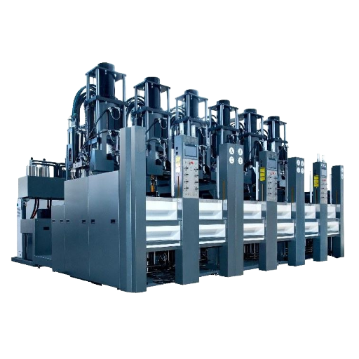
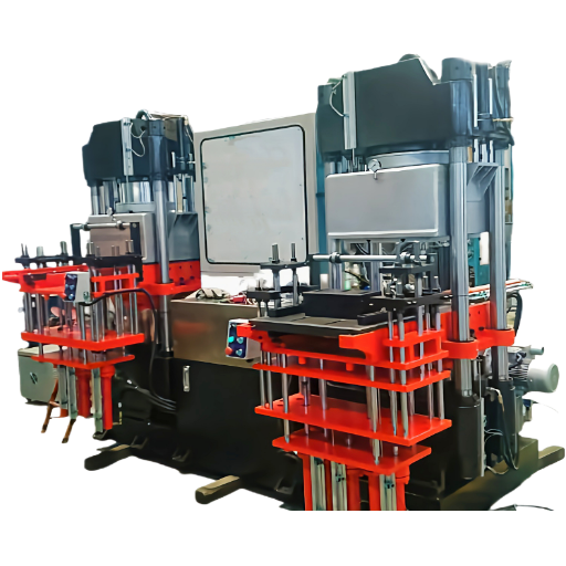
Rubber compression molding is a thermoset forming process in which a predefined quantity of uncured rubber, called a preform, is loaded into the cavity of a heated mold and the two members are closed and maintained under pressure until cross-linking of the compound has produced the desired finished shape. It is the traditional and still the dominant process for rubber components over a medium to large scale, e.g. FKM seals, and at low to medium volume levels in manufacturing, together with the larger family of custom rubber molding process methods which covers injection and transfer molding among other routes.
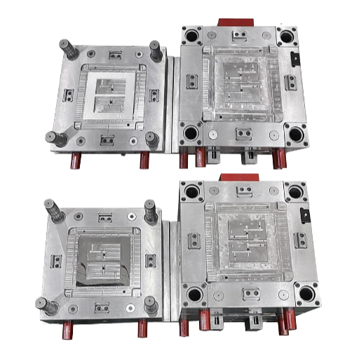
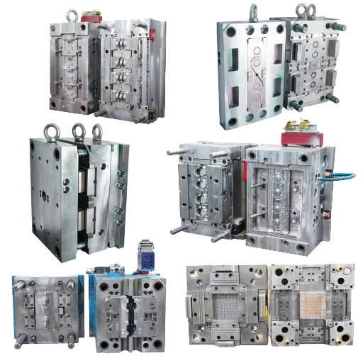
All compression molds are two-plate tools: one top plate and one bottom plate machined out of hot-rolled steel (noted above as for production) or aluminum (for prototype and short runs). The cavity is divided at the parting line, the preform drops into place, and the press closes until the rubber has taken the shape of the mold. Overflow grooves were added to any open cavities to vent out extra excess.
Once the cure is complete the mold is opened and the part is ejected along with its flash ring.
Based on our average quotations, a Tier 1 automotive supplier that we commonly quote requires by volume about 8,000 per year of FKM fuel-line grommets tight chemical resistance, moderate tolerance, small part. Compression always wins that volume because the FKM tooling amortization on a traditional injection press would wipe out the per part cost at that level of production, whereas a 16-cavity compression mold pays for itself in the first 1,500 pieces. This is what the process is designed for.
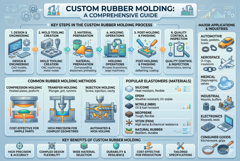
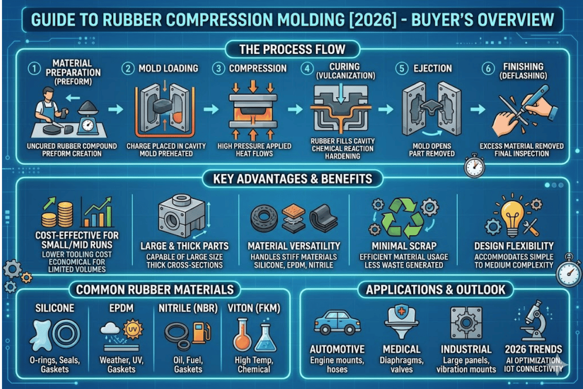
How Rubber Compression Molding Works (Step by Step)
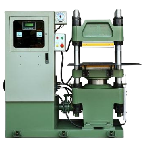
There are six stages in the compression cycle and each of them has a parameter window for dictating whether the finished part is thrown away as scrapped parts or kept as a good job. Today presses work with a PLC maintaining temperature, pressure & dwell time within this tolerance window either close to the compound & the geometry.
- Compound mixing and preform cutting. Uncured rubber compound is cut into preforms sized to match the cavity volume, typically to within ±2% by mass. Too little material produces voids and short shots. Too much produces excess flash and backrind risk. A typical rubber molding shop audits preform weight every 30 minutes.
- Loading the heated mold. The preform is inserted directly into the lower cavity, which is positioned on a steam- or electrically-heated platen. Large preforms are loaded by hand; small multi-cavity molds are handled with a drop-in plate, which lugs every slug into position simultaneously. On shared platens with 15 or more mold cavities, even loading matters — one mis-loaded slot in a corner can drive down the platen temperature by several degrees.
- Press closure. The top platen moves downward. As the press closes, the preform heats and presses simultaneously. Clamp pressure is raised to the desired level and the preform flows outward in search of the cavity, with excess compound venting through overflow grooves at the parting line.
- Curing (vulcanization). The compound cross-links under heat. The general ratios for your typical elastomer are circa 150-200C and 2,000-4,000psi for 3-15min, depending on the compound type and thickness as shown in ScienceDirect documentation of compression molding (our note: there are very similar cycle envelopes for thermoset molding). Cure specification testing is conducted per ASTM D5289 using a die-moving rheometer.
- Mold opening. The mold is released and the upper platen moves away. The cured part is lifted from the cavity along with the flash ring. Air- or hydraulically-assisted are used on deep cavities or parts requiring wide flash widths.
- Deflashing and inspection. The flash ring is cut from the part, usually by cryogenic deflashing for tight-tolerance parts, tumble deburring for mass-production parts such as gaskets. Dimensional inspection and visual inspection for defects are then conducted, documented on sampling statistics per IATF 16949 for automotive work.
How Does Rubber Compression Molding Work in Under 5 Minutes?
The above is a molding cycle in which you take the six steps; pre-form, load, close, cure, open, deflash, and squeeze it into a single 3 to 15 minute pace. Preformed rubber is placed into a heated mold cavity, the cavity is closed at 2,000-4,000psi and 150-200C, and the rubber crosses links into its final shape. When the dwell period concludes, the mold is opened and the cured part is removed and deflashed. Cost-wise, this cycle takes longer than rubber injection molding over a single part but the tool is cheaper, which is the driving factor behind compression molding dominating short- run and large-for-mass-production applications.
Technical Note – Verifying the heat history. ASTM D3182 sets the default cycle for testing elastomers at 340-375F, 700-3,000psi, 1-10min. The actual production cycle is determined from the empirical data of rheology testing and on-press parameters, with stark mold temperature differentials of more than 5C across a cuff and other areas being the primary cause of under cure. The result is udercure, which can be checked by inserting a thermocouple.
“A rubber press with a PLC is not a luxury – it is the minimum. You cannot defend a part in the field if you cannot prove the mold held its temperature, pressure, and dwell for every cure during that production run.”
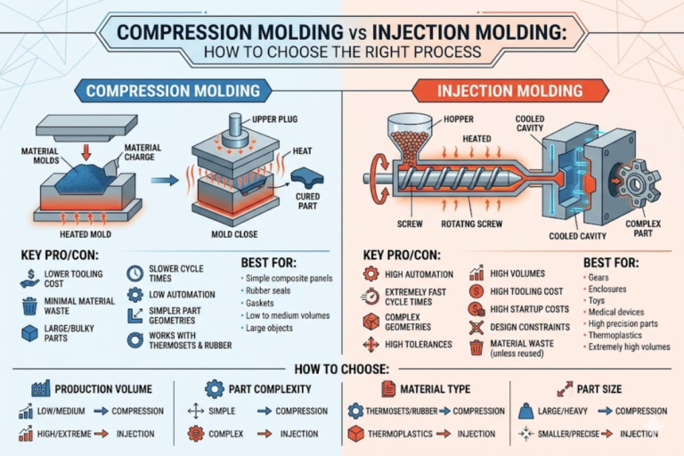
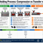
Compression vs Injection vs Transfer Molding: A Decision Framework
The three main forms of rubber processing share the same chemistry but differ dramatically in expense and tolerance. The table below uses shop-typical ranges that reflect what you will actually see on a quote sheet, not marketing generalities. If you have not yet size your order, you can start with the comparison matrix on our rubber processing comparison matrix.
| Criterion | Compression | Transfer | Injection |
|---|---|---|---|
| Tooling cost | $2k–$15k | $8k–$30k | $15k–$80k |
| Cycle time | 3–15 min | 2–6 min | 1–4 min |
| Best volume / year | <25,000 | 5,000–100,000 | >50,000 |
| Flash waste | 5–15% | 8–12% | 1–4% |
| ISO 3302-1 class | M2–M3 | M2 | M1–M2 |
| Large part capability | Up to ~760 mm | Up to ~300 mm | Up to ~300 mm |
In house shop ranges assembled from RPM Rubber Parts, Rubber-Group.com, and our own quoting data. Your part geometry and compound will fit into one of these envelopes.
Which Rubber Molding Process Is Best for Low-Volume Parts?
For annual volumes under about 5,000pcs, rubber compression molding is almost always the right answer. Its tooling is the cheapest of the three, so a short run amortizes the mold without the per-part price exploding. Once you get over roughly 25,000pcs a year with tight tolerances, reduction offlash waste, and thin-wall geometry rubber injection molding begins to win on cycle time. Transfer molding fills the middle band – 5,000 to 100,000pcs where undercuts or inserts make injection too aggressive.
The myth that injection is always faster per part. It is – per cycle. But a rubber compression molding mold costs a fraction of an injection mold. If you divide the tool price by the annual volume, compression wins below roughly 25,000 pieces a year even though its cycle is 3x longer. Most procurement decisions that go wrong on this process go wrong because someone compared cycle times without amortization. Our team’s selection logic is in the elastomer compound selector.
Quick decision rule. If your part is larger than 300mm diagonal, or your annual volume is under 5,000, or your compound is a high-durometer FKM or bulky silicone – pick compression. If your tolerance target is tighter than ISO 3302-1 Class M2 or your cycle economics need to sit under two minutes – pick rubber injection molding. If you need both – consider rubber transfer molding as a bridge.
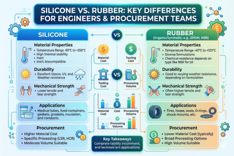
Elastomer Material Selection for Compression Molding
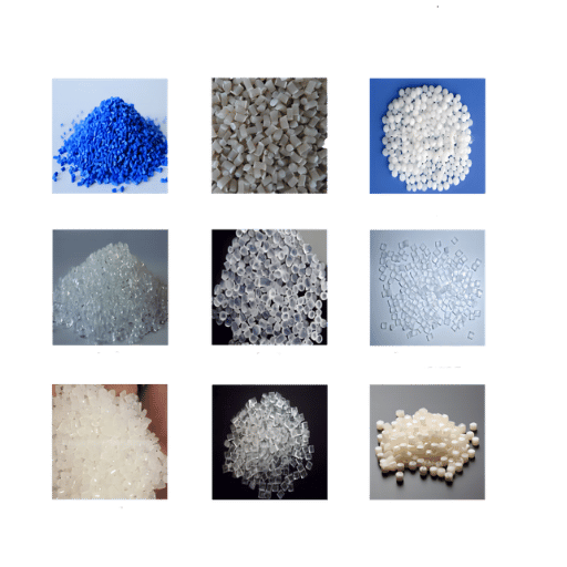
Compression molding is compound-agnostic. Practically every thermoset elastomer can be compression-molded – the question is whether the flow, cure system, and hardness of the compound make it the most economically advantageous fit for the process. The table below couples the six most common rubber compounds with their operating temperature envelope and a typical application. Each compound should be specified against an ASTM D2000 line callout so that material, heat resistance, and fluid resistance are captured in a single string.
| Elastomer | Temperature range | Key property | Representative application |
|---|---|---|---|
| EPDM | −50 to +150 °C | Ozone, weather, steam resistance | Automotive weather seals, HVAC gaskets |
| NBR (Nitrile) | −40 to +120 °C | Oil and fuel resistance | Fuel gaskets, hydraulic seals |
| FKM (Viton) | −20 to +230 °C | Chemical and high-heat resistance | Aerospace, oil & gas, chemical plant |
| Silicone | −55 to +230 °C | Biocompatibility, flexibility | Medical, food-grade, LED sealing |
| Neoprene | −40 to +120 °C | Flame retardance, moderate oil | Marine, adhesive backings, bellows |
| Natural Rubber | −40 to +80 °C | High tear strength, dynamic fatigue | Vibration isolators, engine mounts |
Can You Compression Mold Silicone Rubber?
Yes – compression molding is one of the oldest and most reliable ways to shape silicone rubber, especially high-consistency silicone (HCR) in medical, food, and LED sealing applications. Silicone compression molding runs at 160-200C with curing times in the 3-10min range depending on thickness. Since silicone has lower green strength than the carbon-black-filled organic rubbers, preform handling should be very careful – modern presses use vacuum-assist cavities to support the uncured slug through mold closing. Liquid silicone rubber (LSR) is normally injection-molded rather than compression-molded because its lower viscosity benefits from the pumped injection process.
The other unknown variable is compound availability. As an example, carbon-black-loaded NBR flows quite differently than a mineral-filled silicone at the same nominal viscosity. Our EPDM vs NBR vs FKM property comparison details cure system, filler loading, and compression set behavior for the most common specification scenarios, and the rubber durometer selection guide details how Shore A values alter flow during mold closure.
The Compression Molding Tolerance Reality Matrix
It can be stated that Compression molding tolerance expectations are the number one cause of quoting disputes in this industry. Most engineers come into the quoting room with “injection mold tolerance intuition” and blame the shop when the compression molded part is 0.3mm out of a 0.1mm drawing spec. The real truth is that both numbers are right—they are just defining different classes of tolerance.
The international reference is ISO 3302-1:2014, which sets out four dimensional tolerance classes for moulded rubber products. It is summarized in the table below as the Reality Matrix: what each class actually means to a rubber compression moulding part, and what you can reasonably expect to see on the drawing.
| ISO 3302-1 Class | Tolerance envelope | Achievable with | Reality for compression molding |
|---|---|---|---|
| M1 (high precision) | ±0.10 to ±0.35 mm | Injection, ground tools | Rarely achievable by compression — expect disputes |
| M2 (precision) | ±0.15 to ±0.40 mm | Best-case compression, new steel tool | Possible on small parts (<50 mm), not on flash dimension |
| M3 (general) | ±0.25 to ±0.80 mm | Typical compression production | The default class for most quotes — specify here unless you must go tighter |
| M4 (coarse) | ±0.50 to ±2.00 mm | Prototype, aluminum tools, oversized parts | Reasonable for prototype aluminum tools and very large parts |
Two rules are buried within that table that 9 times out of 10 won’t make it onto a competitor’s blog. First, tolerance doesn’t stay the same across the part — a 10 mm feature on an M3 part tolerates ±0.25 mm, while a 250 mm feature on the same part can tolerate up to ±0.80 mm. Specify the ISO class on the drawing, not one global tolerance.
Second, a dimension that crosses the parting line is a whole other story. Any dimension crossing the parting line inherits an additional ±0.05 to ±0.15 mm of variation from flash thickness, tool wear, and clamp alignment. On a drawing, flash-line features should be given an ISO class one grade looser than fixed dimensions.
What Tolerance Can Rubber Compression Molding Actually Hold?
In production, rubber compression molding reliably holds ISO 3302-1 Class M3 — roughly ±0.25 to ±0.80 mm depending on nominal dimension. Class M2 (±0.15 to ±0.40 mm) is achievable on parts under 50 mm with a freshly cut steel tool and a mature compound, but only on features that don’t cross the parting line. Class M1 precision is unrealistic for compression molding — if your drawing calls out M1, specify rubber injection molding instead, or plan for heavy scrap on every build. Cure shrinkage runs from 1.8% to 4.5% depending on the elastomer family, and that shrinkage is baked into the mold at the cavity-cut stage.
Engineering Note — The “tight tolerance” trap. Without an ISO 3302-1 class on the drawing, the phrase “tight tolerance” is meaningless. A reputable rubber molder will not approve a drawing requesting ±0.05 mm on a compression-molded dimension without a written deviation note. If you come across one who does, ask them to see what their rheometer cure window is — the answer will tell you whether or not they are familiar with their own process.
Common Defects in Rubber Compression Molding and Their Root Causes
Each and every compression molding defect has a documented root cause, and on a well-managed shop floor the solution to the problem is a 20-minute parameter adjustment, not a total mold rebuild. The 6 JEG-related defects listed below account for approximately 90% of batch rejects in a typical production environment. Our own engineering work-flow for creating molds for compression molding of Engelhardt products, shown on the Engelhardt custom rubber molding page, classifies almost every jump from accepted sample to rejected batch according to one of these root causes and demonstrates the temperature/dwell/time solution and its effect on the compression molded part.
- Flash on parting line – preform volume exceeds cavity volume by approximately 15%. Overfilled preform produces excess mass that must escape in the overflow grooves. Trim off excess preform material and widen the overflow groove cross-section. Some flash (up to 15%) is desirable in compression molding, as it is the cheapest way to vent air from the part.
- Backrinding (torn flash on large, thick portion), 8-12 times become common failures than any other type in a rubber molder’s experience. When diagnosing a backrinding problem it is important to remember that this is the defect most often confused with increased depressurization rate. It is actually caused by the outer skin curing faster than inner detail and prematurely cracking the parting line. Corrective action for backrinding need not involve press speed modifications – rapid bump-cycle (shock the mold open) venting for higher dwell/longer cure time will correct backrinding without creating other product issues.
- Porosity and voids in molded product – entrapped air from a lack of adequate venting. Every cavity in the mold must be released to atmosphere via vent grooves of 0.1-0.2mm thickness, also consider the application of vacuum assist or assist/primer for delicate, critical parts. Review initial preforming and loading procedures to eliminate trapped air pockets.
- Incomplete cure – suspicion is mold temperature has climbed more than 5C, or the cure time has been shortened. Conduct a thermocouple survey across the mold platen, and confirm the Time/Temperature/Pressure curing conditions in the ASTM D 5289 rheometry curve before restarting production. An under cured part, while initially passable visually, will fail a compression set test 2 weeks after cure.
- Knit lines – when two or more preform slugs are injected alternately and fail to flow together within the first 2-10 minutes of rising cure temperature. Redesign to a single preform slug whenever possible, or extend flow duration by early mold closure at a higher temperature. Knit lines are the most dangerous of the molding defects, as they mimic a visual cosmetic line but tend to be areas of fatigue concern.
- Delamination on rubber-to-metal bonded parts — substrate contamination or stale Chemlok primer. Plasma clean the substrate before priming and verify primer lot dates. Detailed substrate prep protocol is covered on our rubber-to-metal bonded components page.
Case history – we recently put 1200′ of a batch of 2,000 NBR hydraulic seals on the microscope, and at 12% flash rate the batch failed our incoming quality inspection and was rejected. Our specification required a 0.25mm maximum flash since the preform was entered 15% over an ideal density; humidity contamination of the backing compound had been stacked during transfer to the press. Corrective action was to cut 20 minutes off our preform weighing cycles, and run the seals again. Total equipment time required was an operator shift. You will almost certainly discover that most so-called tool problems in compression molding are material or preform design related.
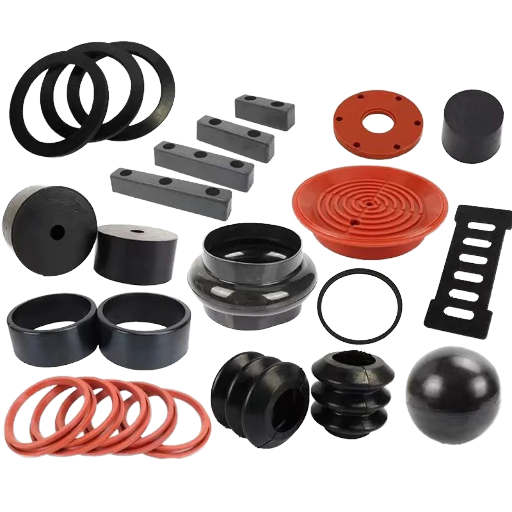
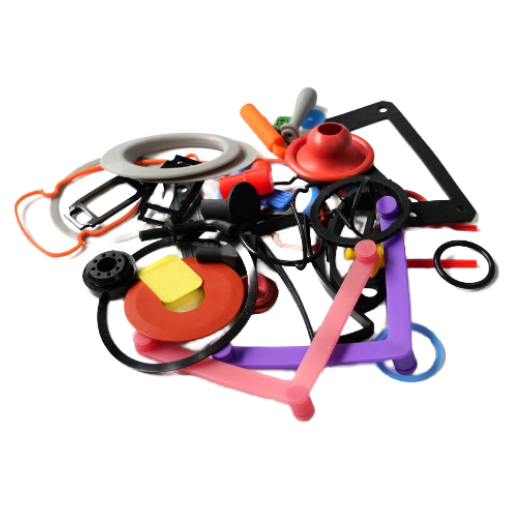
Applications of Rubber Compression Molding by Industry
Rubber compression molding is the unchallenged champion for practically all industries using rubber seals, gaskets, or vibration parts. The part-size envelope is between 0.6mm – 762mm (0.024in – 30in), broader than both transfer and injection molding has the resources to engineer the shape around. Below are the 5 industries where compression reigns.
- Automotive – EPDM weather seals, NBR fuel grommets, FKM transmission O-rings. Compression is the default for any automotive part over 150mm or for short-run certification builds. Our shop ships under IATF 16949, the Tier 1 automotive quality management standard.
- Aerospace – FKM and silicone fluid line seals, MIL-spec gaskets (AS568 O-ring series), and vibration-dampening bushings. Aerospace parts are often small and in need of perfect trace-ability, which compression molding handles via batch-numbered preform lots and rheometer charts retained per lot.
- Medical device manufacturing – platinum-cured silicone syringe stoppers, FDA-grade bumpers, and cleanroom-moulded gasket components. Silicone compression molding is the cleanroom default because the closed mold removes operator contact with the curing compound.
- Oil and gas – large-OD flange gaskets (over 300mm), wellhead elastomer packers, and high-durometer FKM seals for hot-service applications. Oil-and-gas is where the compression-molding size envelope gets its true value because injection presses simply can’t reach these sizes.
- Industrial – vibration isolators, custom bumpers, conveyor skirting, and machine-guard gaskets. Most of these parts are produced in quantities under 10,000 per year, pretty much the sweet spot for compression molding.
Our facility produces in all 5 of these verticals. The numbers (26,000 sqm in China, 60,000 in Thailand, 80 vulcanizing machines, 500 molds cut per year, 3,000 tons of rubber annually) tell the story as to why our aerospace-grade compression molded seals share a work cell with high-volume automotive gaskets. The same press will run a medical silicone stopper in one shift and an oil-and-gas packer in the next. That sort of product-follow-the-pressure approach is the ideal when manufacturing in compression.
Cost Drivers and When to Choose Compression Molding
Industry cost models for rubber compression molding regularly show 4 costs categories that sum to the given per-part quote – the numbers below are shop-typical for a mid-volume production run: remember that your shop will be different, driven by compound, cavity, and labor- and that the ratios will change accordingly. Do expect a “how much do you want us to charge for” kind of debate afterward – confidence is a customer savior
- Compound cost – usually 35% to 55%. This is typically the most expensive line in the model. FKM stands ~$8 for every dollar of EPDM. Material choice really pushes the envelope here.
- Tool amortization – usually 10% to 35%. At 1,000 parts a year, a $10,000 tool costs $10 per part. At 20,000 parts a year, the same tool costs $0.50. Cheap tooling is decisive at low volume.
- Labor (deflashing, inspection, packaging) – usually 15% to 25%. Most of this line is deflashing. Tumble deburring is best per-part for high volume parts; cryogenic deburring gives the lowest costs per-part for small-batch productions.
- Press time – usually 8% to 18%. Compression’s longer press cycle time eats into this ratio; however, the lower capital investment on presses offsets long-term.
This condition based triage below is how our quote engine actually decides between compression, transfer, and rubber injection molding. It is not a rule – it is a first step in your discussion with your design engineer.
Choose rubber compression molding when:
- Annual volume is below 25,000 pieces
- Part is over 150 mm. in any dimension (or the total OD is over 300 mm)
- Tolerance target is ISO 3302-1 Class M3 or looser
- Compound is high-durometer FKM or high-viscosity silicone
- Tooling budget sits under $15,000
Reconsider (injection or transfer may win) when:
- Annual volume climbs above 50,000 pieces
- Tolerance target is tighter than ±0.10 mm on any feature
- Geometry has aggressive undercuts or insert components
- Thin-wall sections below 1.5 mm dominate the part
For compression molded parts, a 500-piece prototype run costs 30% to 50% less than a similar run on the injection press after the tooling costs are amortized, and delivered in 3 to 5 weeks compared to 6 to 10 weeks for injection tooling. For our custom rubber molding quote process, compression can support approximately 40% of yearly demand. This is the cost envelope used to develop this method, and why compression is our first choice for most parts when a customer submits a new drawing.
Frequently Asked Questions
How much does rubber compression molding tooling cost?
Compression molding tooling costs range from $2,000 to $15,000 based on cavity count, shape complexity, and material selected. An aluminum single cavity prototype mold will be at the low end of this range, while a hardened steel 64 cavity production mold with appropriate misting, overflowing, and center gate features will be at the high end of this range. Compare the reported tooling costs to $15,000 for a typical hot-runner injection mold, which will cost more than $80,000.
Is compression molded rubber strong enough for high-pressure applications?
Yes – high durometer FKM or HNBR compression molded seals can readily support pressures over 10,000 psi in many oil-and-gas applications. Aerospace AS568 O-rings are qualification rated for hydraulic pressures well above the typical industrial working ranges.
Can rubber compression molding produce rubber-to-metal bonded parts?
Yes. We start by plasma cleaning the metal insert, then applying a bonding primer such as Chemlok, and placing it into the cavity. The rubber preform then goes on top of the insert, is pressed into the cavity, then during the normal cure cycle, the primer provides a chemical weld line that can often outlast the part itself.
What is the minimum order quantity for compression molded rubber parts?
Most rubber molders will insist on a 500 piece mini order as a minimum to amortize tooling, but we have built numerous flight qualified parts in quantities of 200 to 300 to insure the design will perform to expectation in rigorous testing and use before we build volume. The contractor factory will tell you what their minimum order quantity is, to see if you want to work the lower limits where tooling cost amortization is concerned.
How long does rubber compression molding take from design to first article?
A typical design to first article timeline for a compression mold part is 3 to 5 weeks, which includes about 2 to 3 weeks for cut/finalize/time sample/test fit, and 1 to 2 weeks for deflashing and inspecting the samples. This compares favorably to a 6 to 10 week timeline for typical rubber injection molding.
Does rubber compression molding produce flash?
Yes, and it is normal. We’ve found that 5% to 15% flash by mass is typical for a compression mold process producing precision parts, which is then blown off in a cryogenic deflashing operation in the case of precision parts. The regular part mass is then reduced by simple tumble deburring in the case of gasket parts. Flash by itself should not be judged as a defect, and is in fact a good indicator that the rubber filled the entire cavity and vented the air through the overflowing. Parts with no flash can some times be discovered to have internal voids.
Need a compression-molded rubber part quoted?
Engelhardt’s engineering team considers all drawings using ISO 3302-1 tolerance classes, ASTM D2000 material callouts, and pure compression, transfer and injection cost models prior to quoting. Before submitting your cutpiece drawing to Engelhardt, please upload it here for a 48-hour turn around time.
A note on the numbers in this guide. Cycle-time, tolerance, and cost band ranges within this article are quoted from, or taken directly from ISO 3302-1:2014 and ASTM D2000 / D3182 / D5289 standards, from peer-reviewed academic citations (ScienceDirect), and from Engelhardt’s own production quoting data across 80+ vulcanizing presses. The quoted envelopes reflect typical shop conditions – any specific geometry, compound, and press will land within those envelopes, but projects almost always fall on an edge case. If your drawing bears a tolerance or cost number the loads are aware of, request a written deviation review instead of a generic quote.
References & Sources
- ISO 3302-1:2014 — Rubber: Tolerances for products — Part 1: Dimensional tolerances — International Organization for Standardization
- ASTM D2000-22 — Standard Classification System for Rubber Products in Automotive Applications — ASTM International
- ASTM D3182-22 — Practice for Rubber Materials, Equipment, and Procedures for Mixing Standard Compounds and Preparing Standard Vulcanized Sheets — ASTM International
- ASTM D5289-19a — Standard Test Method for Rubber Property — Vulcanization Using Rotorless Cure Meters — ASTM International
- Compression Molding — overview — ScienceDirect (Elsevier academic reference)
- Temperature Profile in Rubber Injection Molding – PubMed Central (U.S. National Institutes of Health)
- Rubber Manufacturers Association — Dimensional tolerance tables (RMA)
Reviewed by the Engelhardt Engineering Team
Guangdong Engelhardt Rubber & Plastic Technology Co., Ltd. – formed 2009. 80+ vulcanizing machines and 400+ injection machines across dual sites in China (26,000sqm) and Thailand (60,000sqm). Produces 3,000tons of rubber annually, with 500 new molds/year. Certs include ISO 9001, IATF 16949, FDA, LFGB, NSF, UL, KTW, WRAS, ASTM. Types of composites handled include EPDM, NBR, FKM, silicone, neoprene and natural rubber compression, transfer and injection moldings.
Related Articles
- Rubber Injection Molding — Process, Tooling and Cost Envelope
- Rubber Transfer Molding — Where It Beats Compression and Injection
- Rubber-to-Metal Bonded Components — Substrate Preparation and Primer Selection
- Rubber Molding Process Comparison Matrix
- Rubber Elastomer Compound Selector
- Rubber Material Durometer Selection Guide