Get in Touch with Engelhardt

Overmolding is an injection molding process that molds a second material over an existing substrate to make one finished part, a soft grip over a rigid handle, a sealed housing, or rubber bonded to a metal core. This guide to overmolding explains how the process work, how it differs from insert molding and two-shot molding, which materials bond to which, the design rules that keep parts from delaminating, and what an overmolding program actually costs. It’s written from a production molder’s bench rather than a prototype quote calculator.
Quick Specs: Overmolding at a Glance
| Process family | Overmolding, insert molding, two-shot (2K) molding |
| Common substrates | ABS, PC, PA (nylon), PP, PBT, glass-filled grades |
| Common overmolds | TPE, TPV, TPU, liquid silicone rubber (LSR), EPDM, nitrile |
| Typical overmold wall | ~0.5–4 mm (uniform sections preferred) |
| Dimensional tolerance | ±0.05–0.10 mm on controlled features |
| Bond types | Chemical, mechanical, or both (primer/adhesive for silicone & rubber) |
Capability envelope per ISO 19095 plastic, metal adhesion methods and Engelhardt production data.
What Is Overmolding?
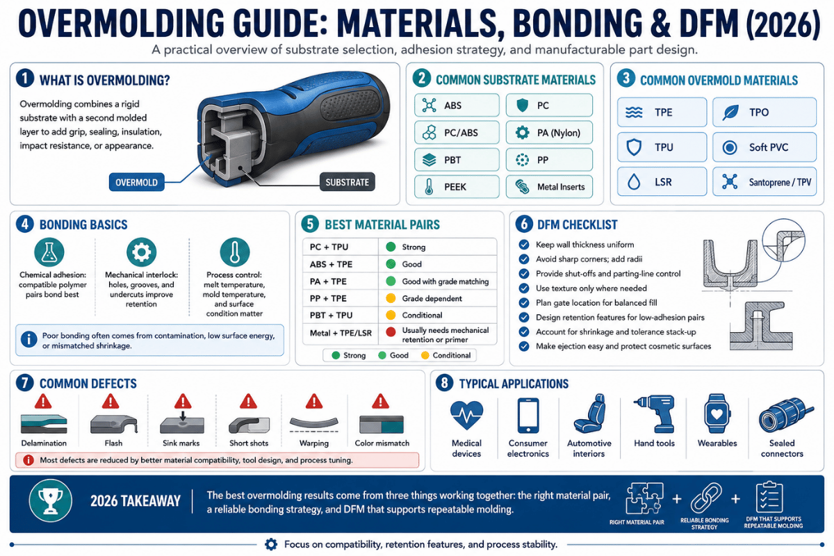
At its core, overmolding combines two or more materials into a single part by molding a second material, the overmold, onto a first material called the substrate. Usually the overmold is a soft, rubber-like resin such as a thermoplastic elastomer (TPE) molded over a rigid plastic, but it can also be silicone or vulcanized rubber. That gives one part with properties no single resin can deliver: a hard structural core with a soft, grippable, sealing, or vibration-damping surface. Because the second material is molded directly onto the first, overmolding removes the downstream step of gluing or assembling two parts by hand. As a manufacturing process, engineers use overmolding to make one plastic part do the work of several; common overmolding applications include soft-touch grips, seals, sealed housings, and vibration mounts.
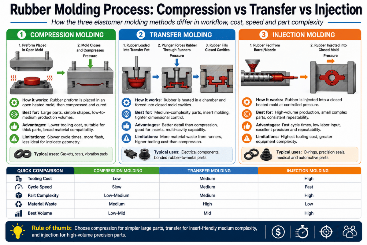
It helps to separate three terms that get used interchangeably. Overmolding molds a second material over a finished plastic substrate. Insert molding involves placing a pre-formed metal or plastic insert into the cavity and injecting plastic around it in a single shot. Two-shot molding (also called 2K molding) injects two materials in one machine cycle using a rotating or multi-shot tool, distinct from compression molding, which cures a material charge under heat and pressure. Together, insert molding and overmolding cover most multi-material parts. All three are forms of the broader plastic injection molding family, and all three eliminate a separate assembly operation, but only when the part is designed for the process from the first sketch.
💡 Pro Tip
Every overmolded part lives or dies at one place: the interface between substrate and overmold. Before choosing a press or a color, decide how the two materials will bond — chemically, mechanically, or both. That decision drives everything downstream.
Overmolding vs. Insert Molding vs. Two-Shot Molding

Engineers and program managers keep hitting the same disagreement: engineering wants the strongest bond, the program want the lowest piece price, and the two pull in different directions. These three multi-material processes are not interchangeable, picking the wrong one show up either as a tooling bill that’s too high for the volume or a feature that can’t be molded at all. Our comparison below put the trade-off in concrete terms, and the on-page overmolding, insert molding or two-shot process selector turns it into a quick recommendation for your part.
| Decision criterion | Insert molding | Overmolding | Two-shot (2K) |
|---|---|---|---|
| What it joins | Pre-formed metal/plastic insert + one plastic shot | Substrate + a second material molded over it | Two polymers, two shots, one cycle |
| Interface bond | Mechanical (insert geometry) | Chemical + mechanical | Chemical, in-cycle |
| Relative tooling cost | Lowest | Moderate | Highest (rotary/2K tool) |
| Volume where it pays | Any volume (threaded/contact parts) | Low to high (broad material range) | Very high (often >10,000–100,000/yr) |
| Typical parts | Connectors, threaded bosses, contacts | Soft-grip handles, seals, sealed housings | Multi-color caps, high-volume buttons |
Volume thresholds reflect published two-shot vs. pick-n-place economics and Engelhardt production practice.
The Bond-First Process Triangle
Instead of starting from price, our engineers start from the joint the part actually needs, a simple way to choose among the three process:
- Needs a threaded fastener or an electrical contact? → Insert molding, at any volume. The metal does a job plastic can’t.
- Needs a soft-touch grip, a seal, or a broad material range at low-to-high volume? → Overmolding. Simpler tooling keeps the upfront cost down.
- Running into the hundreds of thousands per year with a stable design? → Two-shot. Single-cycle efficiency pays back the heavier tool.
Some geometries rule one process out entirely, a co-molded contact may rule out overmolding; a sealed multi-material shape may rule out two-shot. That’s why process selection belongs in the first design review, not after the tool is cut.
What Is the Difference Between Overmolding and Insert Molding?
Insert molding places a pre-formed component, often a threaded brass bushing or an electrical contact, into the mold, then injects plastic around it in a single shot; the joint is purely mechanical, because there’s no chemical bond between metal and plastic. Overmolding molds a second plastic or rubber layer over an existing plastic substrate, and that bond can be chemical, mechanical, or both. Put simply: insert molding adds a functional metal feature; overmolding adds a second soft or rigid layer such as a grip or a seal. Many real parts use both at once, a sealed connector with brass contacts (insert molding) and a TPE strain relief (overmolding) on the same shot sequence.
Overmolding Materials and Substrate-to-Overmold Bonding
An overmolded part fail in the field for one reason far more often than any other: the bond between substrate and overmold was an afterthought. A soft grip peels at the edge; a sealed connector let water in at the interface; a TPE button delaminates after thermal cycling. Almost always, the cause is a material pair that was never tested for compatibility, or a substrate with no mechanical interlock to back up a weak chemical bond. Choosing overmolding materials therefore starts at the interface, not at the press.
There are two ways layers bond. A chemical bond forms when the two polymers are compatible and the molten overmold wet the substrate surface, peer-reviewed work on injection overmolding shows bond strength rising with molecular interdiffusion at the interface, which in turn rises with melt temperature and contact time (NIH/NCBI study on overmold bonding strength). A mechanical bond relies on undercuts, through-holes, or texture that the overmold flows into and grips. Together they make the strongest, most repeatable overmolded parts. This chart is the starting point our engineers use during design review.
| Overmold material class | Typical hardness | On ABS / PC | On PP / PE | On metal insert |
|---|---|---|---|---|
| TPE (styrenic / SEBS) | 20–90 Shore A | Chemical + mechanical | Mechanical (interlock advised) | Mechanical |
| TPE (TPO-based) | 40–90 Shore A | Mechanical | Chemical + mechanical | Mechanical |
| TPV (Santoprene-type) | 35–90 Shore A | Mechanical | Chemical + mechanical | Mechanical |
| TPU | 60 Shore A–60 Shore D | Chemical + mechanical | Mechanical | Mechanical |
| TPC (copolyester) | 35–80 Shore D | Chemical + mechanical | Mechanical | Mechanical |
| Liquid silicone rubber (LSR) | 10–80 Shore A | Mechanical / primer | Mechanical / primer | Mechanical / primer |
| HCR silicone | 30–80 Shore A | Mechanical / primer | Mechanical / primer | Primer |
| EPDM (vulcanized) | 40–90 Shore A | Adhesive system | Adhesive system | Chemical (bonding agent) |
| Nitrile / NBR (vulcanized) | 40–90 Shore A | Adhesive system | Adhesive system | Chemical (bonding agent) |
| Natural rubber | 30–90 Shore A | Adhesive system | Adhesive system | Chemical (bonding agent) |
Material families, not specific grades; bond classifications align with published compatibility data and ASTM D429 rubber-to-metal adhesion testing. Always validate on your actual resin pair.
Selecting Overmolding Materials
Selecting overmolding materials is a pairing decision, not a single-material one. Because overmolding combines multiple materials in one part, you select materials for the substrate and the overmold together, the combination of materials, not either one alone, decides whether you get a strong bond between the materials or a weak interface. Common overmolded materials span styrenic TPE, TPU, TPV, liquid silicone rubber, and thermoset materials such as vulcanized rubber; each overmolded material wet and grips a given molded plastic substrate differently. Choosing the best materials for overmolding means matching surface energy, melt temperature, and the two materials’ chemistries, different materials that look identical on a datasheet can behave very differently once molded. When no chemically compatible pair exists, designers rely on mechanical interlock, the same logic that makes plastic overmolding onto low-energy substrates work at all.
The pattern that surprises buyers most is that chemical compatibility alone isn’t always enough. Practitioners report that even two very similar grades of the same elastomer can delaminate if melt temperature, surface cleanliness, or time-between-shots are wrong. Low-surface-energy substrates such as polypropylene and polyethylene cause the molten overmold to bead instead of wet, which is why a PP part usually needs a polyolefin-specific TPV, or a designed-in mechanical interlock, rather than a generic TPE.
The Four Interface-Failure Modes
When an overmolded part fail, it’s almost always one of these four, ranked by how often we see them on incoming parts that were molded elsewhere:
- Edge peel. An exposed overmold edge lifts and propagates. Fix: recess the edge behind a lip of substrate.
- Interface contamination / poor wetting. Oils, mold release, or a cold substrate skin stop the chemical bond. Fix: clean (IPA), control time-between-shots, preheat to roughly 80–120 °C, just below the substrate’s softening point.
- Thermal-cycle delamination. Mismatched expansion pulls the layers apart in service. Fix: pair compatible chemistries and test after environmental conditioning, not just as-molded.
- No mechanical backup. A weak chemical bond with nothing to hold it. Fix: add undercuts, through-holes, or texture so the overmold is keyed in.
Can Silicone or Rubber Be Overmolded onto Plastic and Metal?
Yes. Liquid silicone rubber and vulcanized rubber are routinely overmolded onto plastic substrates and metal inserts, alongside TPE, TPV, and TPU. What differs is the bonding route: silicone and rubber usually bond mechanically or through a primer/bonding agent rather than by direct chemical adhesion, so the substrate geometry and surface preparation must be designed in from the start. LSR, for instance, cures in the tool at roughly 150–200 °C, well above the 230–290 °C melt range of a typical ABS substrate, so the thermal window has to be managed. This is exactly where a molder with in-house rubber capability matters, Engelhardt runs silicone overmolding and rubber overmolding on more than 40 vulcanizing machines, and treats rubber-to-metal bonding as a core process rather than a subcontracted one.
Insert Molding and Threaded Inserts: Designing for Retention

For threaded inserts, pull-out and torque resistance come from the plastic boss around the insert and the insert’s knurl pattern, not from the screw thread alone. Diamond-knurled brass inserts hold substantially better than smooth or self-tapping ones, because molten plastic flows into the knurl and form a mechanical key. Get the boss too thin and the wall cracks during molding or in service; too thick and it sinks.
The 2.5x Boss Rule
Sizing the boss
As a working rule, size the plastic boss outer diameter at roughly 2 to 2.5 times the insert outer diameter. A material-maker rule of thumb puts the boss OD at 2.0–2.5× the insert, and boss wall thickness around 40–60% of the part’s nominal wall. Worked example:
A brass insert with a 6 mm outer diameter → target a boss OD of about 6 × 2.5 = 15 mm (a 12–15 mm range is the working window). On a 2.4 mm nominal wall, the boss wall lands near 40–60% × 2.4 mm ≈ 1.0–1.4 mm.
These are starting points. Confirm retention on your actual resin during sampling rather than trusting a generic datasheet.
📐 Engineering Note
There’s no chemical bond between a metal insert and plastic, so insert retention is 100% mechanical. We confirm pull-out and torque on the customer’s actual resin at T1 sampling, and prefer symmetrical diamond-knurled inserts to reduce sink marks on cosmetic faces. For load-bearing inserts, design the boss so the load path run into the bulk of the part, not into a thin rib. An insert-molding boss size calculator is a fast first check before you commit the geometry.
Overmolding Design Rules (DFM)
Good overmolding design is mostly disciplined injection molding design applied to two materials at once. Your substrate has to survive the heat and pressure of the second shot, and the overmold has to wet, fill, and grip without trapping air or shrinking away from the substrate. A few rules carry most of the weight.
- ✔ Keep walls uniform. Substrate and overmold sections both want consistent wall thickness for even flow; thick pockets cause sink and voids.
- ✔ Back up weak chemical bonds mechanically. Undercuts, through-holes, or texture turn an uncertain bond into a reliable one.
- ✔ Keep gates off the bond line. Place gates so flow fronts fully wet the interface instead of meeting at a weak knit line in the highest-stress area.
- ✔ Protect overmold edges. Recess exposed elastomer behind a substrate lip so peeling has nowhere to start.
- ✔ Validate after conditioning. Test bond strength after thermal/humidity exposure, not just on as-molded parts.
Designing for overmolding starts with disciplined part design. This design process bring product design and manufacturing together, so design for manufacturability (DFM) and the key design considerations belong early, not after the tool is cut. Mechanically, the overmolding process run on a standard injection molding machine, but the molding operation adds a second material to the manufacturing process, so the molding design guide your team follows has to account for both shots. Design factors that matter most, uniform walls, mechanical interlock, and gate position, are the same ones that decide whether the process of overmolding yields a clean part or a delamination complaint.
What Is the Minimum Thickness for Overmolding?
There’s no single universal number, because the minimum depend on the material, the flow length, and the tooling. As a practical starting point, overmold sections in the range of roughly 0.5–4 mm mold reliably, with many soft-touch grips living around 1–2 mm; very thin overmold features can be molded but get harder to fill cleanly as the wall drops below about 0.5 mm. A counter-intuitive point worth flagging: a thin, soft elastomer can still feel hard, because perceived softness depends on overmold thickness and flexural modulus, not durometer alone. If grip or cushioning is the goal, give the overmold enough thickness, or add ribs, rather than just specifying a lower durometer. For dimensional questions on the rigid substrate, see our guide to injection molding tolerances.
What Overmolding Costs: Tooling vs. Per-Piece
An overmolding project is quoted in two lines, and most “comparable” quotes diverge once you read into them. One line is a one-time tooling fee; the other is a recurring per-piece price. Total project price equals the tooling fee plus the unit price times quantity, there’s no honest single number that covers both.
Tooling drivers (one-time)
- Part size and number of cavities
- Steel grade and rated mold life
- Mold complexity (transfer, rotary, or 2K)
Per-piece drivers (recurring)
- Material grade and part weight
- Cycle time and press size
- Secondary operations, inserts, and assembly
Two real cost levers hide in the per-piece line. First, labor: at low volume, brass inserts are often loaded into the tool by hand, which is real recurring cost; at high volume, robotic loading and two-shot tooling pull that labor out. Second, vendor count: splitting a part across a substrate molder, an overmold molder, and a separate hardware vendor adds duplicated freight, duplicated inspection, and a tolerance stack that no one owns. Consolidating those into one supplier is frequently where the real savings live, which is the whole premise of Engelhardt’s production-volume overmolding and insert molding services.
“When a buyer hands us a soft-grip handle as three separate part numbers, the first thing we look at is the bond line, not the price. Consolidating the substrate, the overmold, and the metal insert into one tool is where the real cost and quality gain lives, because the interface stops being someone else’s problem.”
Engelhardt Engineering Team
Where Overmolding Is Used: Applications by Industry
Overmolded parts show up anywhere a product need two material behaviors in one part. Four industry patterns cover most overmolded parts:
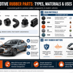
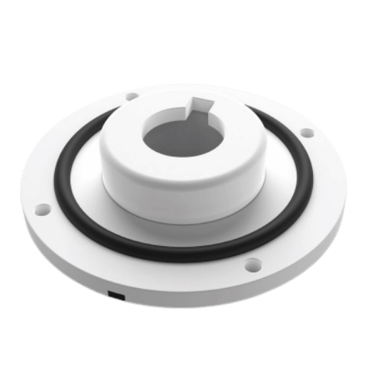
Automotive. Sealing components, bushings, and bonded isolators run under an IATF 16949 quality system with PPAP-style documentation. Take a bonded isolator: it pairs a stamped steel core with a vulcanized rubber overmold to carry load while damping vibration, a textbook automotive rubber part. Electrical and connectors. Cable overmolding and sealed housings guard contacts from moisture and strain; a connector might use insert-molded brass pins plus a TPE strain relief overmolded in the same program, see our notes on electrical and electronic rubber parts. Hardware and consumer. Soft-touch grips on tools and appliances remove a separate grip-assembly step. Medical. Overmolded device components, an overmolded catheter hub is a documented example where the bonding method affects concentricity and kink resistance (US Patent 7,713,260) — often use LSR for biocompatibility and sterilization resistance.
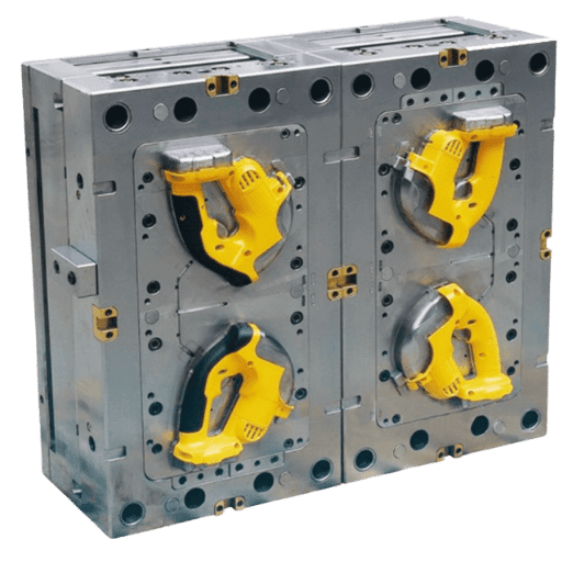
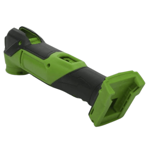
One concrete scenario make the trade-offs real. Consider a power-tool maker shipping 60,000 cordless drills a year, arriving with a three-part grip: a glass-filled nylon housing, a TPV soft grip, and four brass threaded inserts, sourced from three vendors. Field returns show grips peeling at the trigger edge. Consolidated into one overmolding program, the edge is recessed behind a nylon lip, the TPV is swapped for a polyolefin-compatible grade that bonds to the nylon, and the inserts are molded in on the same line. The peel complaints stop, and the buyer issues one purchase order instead of three.
Industry Outlook: What’s Changing in Overmolding
Through 2026, the biggest shift in overmolding isn’t a new material, it’s how buyers structure the supply chain. That load-bearing change is vendor and tolerance-chain consolidation: procurement teams are collapsing the substrate molder, the overmold molder, the insert supplier, and final assembly into one factory, specifically to kill the cross-vendor tolerance stack that causes most multi-material field failures. Labor and freight that hid in a three-vendor structure become visible, and removable, once one supplier owns the whole part.
Two other drivers are worth watching. First, demand for LSR and medical overmolding is pulling primer-bond and cleanroom capability in-house at production molders, because outsourcing the silicone step reintroduces the interface problem this whole article is about. Second, overseas-sourcing scrutiny is rising: buyers are writing virgin-material clauses and tooling-ownership terms directly into the RFQ rather than discovering after the fact that they only paid for cavity inserts or that regrind was blended into a part specified as virgin. The action for a buyer planning an overmolding program now is concrete, lock material grade, steel grade, dimensional tolerances, and full mold ownership into the RFQ before any drawings are surrendered, the same four control points our production-volume overmolding and insert molding services quote against by default. For market context, mold-design and insert-molding service markets are projected to keep growing through the early 2030s, but that’s background to the procurement shift, not the reason for it.
Frequently Asked Questions
Q: What is an example of overmolding?
View Answer
Take a toothbrush: a rigid plastic handle (the substrate) with a soft TPE overmold for grip and comfort. Industrial examples include a power-tool handle with a soft-touch grip, a sealed electrical connector with an overmolded strain relief, an automotive bushing with rubber bonded to a metal core, and a medical catheter with an overmolded hub. In each case, two materials are combined into one part so the product gets properties — grip, sealing, vibration damping, biocompatibility — that no single resin can deliver.
Q: How does overmolding work?
View Answer
First a substrate is produced by standard injection molding. That substrate is then placed in a second mold — by robot in two-shot molding, or by hand in pick-n-place molding — and a second material is injected over it. The overmold bonds to the substrate chemically, mechanically, or both, and the finished multi-material part is ejected as one piece. The key control points are material compatibility, substrate cleanliness and temperature, and gate placement, because those determine whether the interface actually bonds.
Q: Can EPDM be overmolded?
View Answer
Yes. EPDM and other vulcanized rubbers are overmolded onto plastic substrates and metal inserts, but they bond through an adhesive or bonding-agent system rather than by direct chemical adhesion to most plastics. That means the bonding agent, surface preparation, and cure conditions have to be designed in from the start, and the bond is typically verified with a rubber-to-metal adhesion test such as ASTM D429. A molder with in-house vulcanizing capability handles this far more reliably than one subcontracting the rubber step.
Q: Is overmolding expensive?
View Answer
It depends on volume. Overmolding carries a one-time tooling cost plus a per-piece cost, and it often reduces total cost by eliminating a separate assembly step. Below about 10,000 parts, pick-n-place overmolding usually wins on total cost; above that, two-shot tooling starts to pay back.
Q: What are the disadvantages of overmolding?
View Answer
Bond failure is the main risk — delamination or peel when material pairs are incompatible or process control slips. It also adds tooling complexity, a second material to handle, and tighter process windows than single-shot molding. These are manageable with disciplined material selection, mechanical interlock features, and validation after environmental conditioning, but they make supplier capability and DFM review more important than for a single-material part.
Q: Do overmolding materials differ from standard injection-molding materials?
View Answer
They are mostly the same resin families — ABS, PC, nylon, PP, PBT as substrates and TPE, TPV, TPU, LSR, or rubber as overmolds — but overmolding adds one decisive requirement: the substrate and overmold must be compatible as a pair. A resin that molds perfectly on its own can still fail as an overmold if it cannot wet or bond to the chosen substrate. Some TPE grades are formulated specifically for adhesion to a given substrate, and silicone or rubber often needs a primer. That is why overmolding material selection is a pairing decision, not a single-material decision, and why grades should be validated together on real tooling before production.
Why We Wrote This Guide
Engelhardt molds plastic, TPE, silicone, and rubber overmolds onto plastic and metal inserts at automotive production volumes, substrate, overmold, inserts, and assembly under one roof, with more than 40 vulcanizing machines and an in-house lab (Mooney viscometer, rheometer, salt-spray) that lets us verify bond and pull-out strength on real resin. The bond-compatibility chart and the 2.5× Boss Rule in this guide come from our own design-review practice, not a datasheet. Reviewed by the Engelhardt technical team.
References & Sources
- ISO 19095-1:2015, Plastics: Evaluation of adhesion interface performance in plastic-metal assembliesInternational Organization for Standardization
- ASTM D429, Standard Test Methods for Rubber Property, Adhesion to Rigid SubstratesASTM International
- Modeling the Adhesion Bonding Strength in Injection OvermoldingNIH/NCBI PubMed Central
- US Patent 8,329,088, Process for over-molding onto crosslinked polymersUSPTO / Google Patents
- US Patent 7,713,260, Catheter having an overmolded hubUSPTO / Google Patents
- The Materials Analyst, Part 28: Adhesion Failures in OvermoldingPlastics Today
- Adhesion in Hard-Soft Overmolding (Plastics Technology)Plastics Technology
Related Articles
- Silicone OvermoldingLSR and silicone over plastic and metal, with primer and bonding routes.
- Rubber-to-Metal BondingAdhesive systems, surface prep, and bond verification.
- Injection Molding TolerancesWhat to specify on the rigid substrate.
- Process Selector: Overmolding, Insert Molding or Two-ShotMatch your part to the right process.
Sizing an overmolding or insert-molding program for production volume, not a prototype calculator?