
Póngase en contacto con Engelhardt


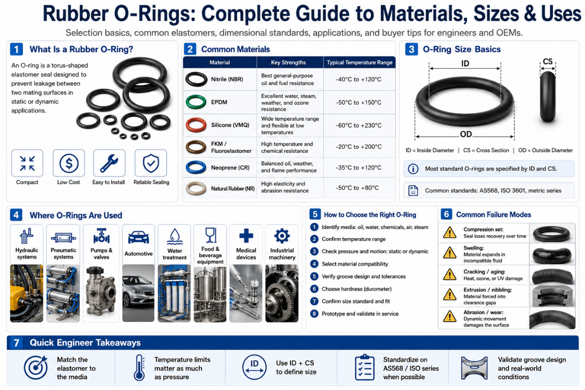
Juntas tóricas de caucho (los pequeños sellos redondos que mantienen las fugas de fluido y gas dentro de un cilindro hidráulico, una tuerca y un perno, un motor a reacción o un satélite). En términos del costo del material, son insignificantes, pero una decisión incorrecta en el proceso de diseño puede resultar en una fuga, pérdida de producción e incluso una falla de campo más valiosa que la pieza misma. Este artículo describe qué es una junta tórica de caucho y cómo funciona, los materiales utilizados en su composición, la designación de una junta tórica, los modos de falla, la frecuencia diferencial de falla y cómo seleccionar la correcta sin la retórica del marketing.
Ya sea que esté reparando una fuga en una bomba o diseñando juntas tóricas para convertirlas en un nuevo producto, se aplica la misma física y está involucrada la misma lista de elastómeros de cinco letras. Tendrás una técnica de selección comprobada que eliminarás al final.
Especificaciones rápidas de la junta tórica de goma
| Forma de sección transversal | Circular (toro) « sellado por compresión en una ranura |
| Sistemas de dimensionamiento | AS568 (imperial, SAE)· ISO 3601 (métrico) « no intercambiable |
| Materiales comunes | NBR (nitrilo), FKM, EPDM, silicona, FFKM |
| Dureza estándar | 70 Costa A (±5); 90 Costa A para servicio de alta presión |
| Rango de temperatura | «65 °C a +316 °C en toda la familia de materiales |
| Clase de aplicación | Estático o dinámico (reciprocante, giratorio, oscilante) |
¿qué es una junta tórica de goma?
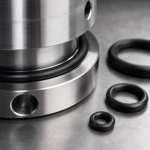
Una junta tórica de goma es un bucle de elastómero con una sección transversal redonda « un toroide en términos geométricos. Se comprime en una ranura mecanizada entre dos partes acopladas para actuar como un sello. Una sección transversal elastomérica se deforma para llenar el espacio, impidiendo el escape de un fluido o gas. Su nombre deriva de ese perfil, no de la forma del anillo.
Las juntas tóricas son el tipo de sello más común utilizado en un diseño mecánico simplemente porque son baratos, simples y de uso múltiple; el sello es bidireccional, la presión se sella desde ambos lados. El uso de juntas tóricas se puede encontrar en todas partes, desde el grifo de la cocina de una casa hasta el sistema de combustible de un automóvil de pasajeros y las juntas segmentadas de un propulsor de cohete sólido.
¿cuál es la diferencia entre una junta tórica y una junta?
Aquí está el punto de confusión más habitual, y la simple verdad es que una junta tórica es una especie de junta, pero no todas las juntas son juntas tóricas. Una junta es cualquier pieza flexible que se coloca en una junta para evitar fugas. Las juntas planas son precisamente eso, colocadas entre dos bridas planas que se mantienen firmemente unidas mediante pernos.
Una junta tórica es una junta mecánica específica que tiene un orificio redondo y se encaja en un espacio o ranura, aprovechando la presión del sistema para mejorar el sello (que se explica a continuación).
En la práctica: utilice una junta plana para bridas grandes, planas y atornilladas; Utilice una junta tórica para juntas ranuradas, especialmente juntas bidireccionales o de alta presión. Las juntas tóricas permiten presiones mucho más altas en una envoltura más pequeña que una junta plana comparable. Las convenciones dimensionales y de prueba para anillos de caucho moldeados se definen en normas como ASTM D1414, los métodos de prueba estándar para juntas tóricas de goma.
💡 Conclusión clave
Una junta tórica es un anillo con una sección transversal circular que encaja en una ranura. Si tienes una junta con una sección de ranura mecanizada y la sometes a presión, entonces casi siempre hay una junta tórica en el lugar para comenzar.
¿cómo sella realmente una junta tórica?
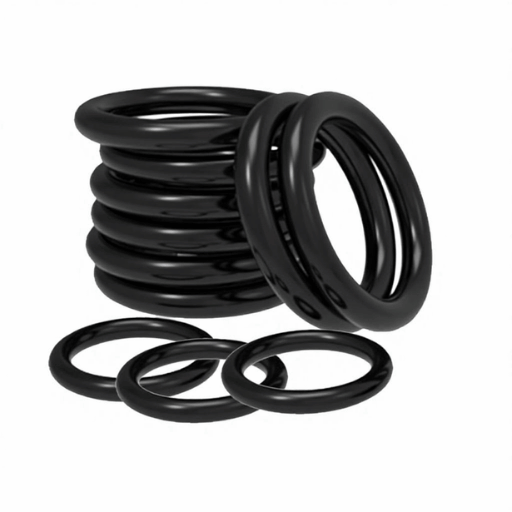
Hay dos etapas en la operación de sellado de juntas tóricas, y ser consciente de ambos pasos es lo que marca la diferencia entre un diseño bueno y uno malo. Ambas etapas se basan en las propiedades de sellado del elastómero: su deformación elástica bajo presión y su recuperación posterior.
Paso uno: compresión mecánica. Cuando se ensambla la ranura, la junta tórica se deforma (aprieta) entre el fondo de la ranura y la superficie de contacto. Esta deformación «la compresión « empuja el elastómero en contacto con ambas superficies y proporciona el primer sellado a presión cero. El apretón se expresa como porcentaje del diámetro de la sección transversal.
Etapa dos 'energización por presión. Ahora llega la hermosa parte de este sistema. A medida que aumenta la presión, la junta tórica incompresible se fuerza a través de la ranura hacia el lado de baja presión.
El elastómero se hincha en el espacio anular y ejerce una mayor fuerza contra las superficies de sellado. La junta tórica utiliza la presión que intenta contener para crear un mejor sello (el nombre de los ingenieros estatales es autoenergizante). Esta es la razón por la que la junta tórica del tamaño adecuado puede contener miles de psi donde una junta plana suelta no puede.
La cantidad de compresión que necesita depende de la aplicación. Muy poco, el sello gotea; demasiado, y el elastómero toma un juego permanente o se extruye en el espacio. Los rangos de diseño típicos son:
| Aplicación | Apretón típico | Acabado superficial (Ra) |
|---|---|---|
| Sello facial estático | 20–30% | 16-32 µin |
| Radial estático (masculino/femenino) | 18–25% | 16-32 µin |
| Reciprocante (dinámico) | 10–20% | 8-16 µin |
| Rotativo (dinámico) | 0–10% | 8-16 µin |
Observe la línea contraintuitiva: los sellos giratorios obtienen el menor apretón de todos. Una compresión excesiva en un eje giratorio creará calor por fricción del material elastomérico. Las juntas tóricas dinámicas requieren una superficie de contacto más lubricada, no una compresión más apretada.
📐 Nota de ingeniería
La relación entre el volumen de la junta tórica y el volumen de la ranura (glándula) debe ser de aproximadamente 60-85%. Un elastómero es casi incompresible y necesita espacio para deformarse. La forma de la glándula, que permite que la junta tórica la llene demasiado, da como resultado un sello “atrapado” que extruye o se enrolla.
Las tablas de tallas de ranuras según la sección transversal AS568 se pueden encontrar en la norma (nunca a mano alzada). El relleno de glándulas puede tener el efecto opuesto si la forma de la glándula se ajusta perfectamente: se evitará que la forma se deforme y el sello podría dañarse.
Materiales de la junta tórica de caucho: NBR, FKM, EPDM, silicona y FFKM
El material es la elección de junta tórica más crítica que hará. Las mismas dimensiones, mecanizadas en el polímero incorrecto, se filtrarán, hincharán, endurecerán o agrietarán en un plazo de tres a doce semanas. Para la mayoría de las aplicaciones industriales, sólo se utilizarán cinco familias de elastómeros y todas ellas están clasificadas según su resistencia al calor y al aceite ASTM D2000 el estándar de referencia para materiales de caucho.
| Material | Rango de temperatura (grado estándar) | Fuerte contra | Uso típico |
|---|---|---|---|
| NBR (nitrilo) | «40 a +125 °C | Aceites de petróleo, fluidos hidráulicos, combustibles | Sistemas hidráulicos y neumáticos, automoción |
| FKM (fluoroelastómero) | «25 a +230 °C | Calor, combustibles, muchos productos químicos, ozono | Procesamiento químico, aeroespacial, motores |
| EPDM | «40 a +135 °C | Agua, vapor, líquido de frenos, intemperie | Fontanería, HVAC, equipos para exteriores |
| Silicona (VMQ) | «65 până la +205 °C | Temperaturas extremas, calor seco | Sellos alimentarios, médicos y estáticos de alta temperatura |
| FFKM (perfluoroelastómero) | hasta +316 °C | Casi todos los medios químicos y agresivos | Servicio de semiconductores y productos químicos agresivos |
Además de los cinco elastómeros, la junta tórica de PTFE también se utiliza en nichos estrechos de servicio químico y de alta temperatura, ya que los compuestos de caucho se llevan a sus extremos, aunque no con la recuperación elástica de un elastómero. Sin embargo, cualquiera que sea el tipo de junta tórica que se elija, la consideración final es hacer coincidir la resistencia química del material con el medio con el que entrará en contacto.
Hay dos hechos materiales que engañan a los diseñadores. En primer lugar, la silicona no es adecuada para el sellado dinámico aunque su temperatura es bastante alta, ya que tiene una resistencia a la tracción muy baja y una resistencia a la abrasión muy pobre, es más adecuada sólo para aplicaciones estáticas. El segundo punto es que FFKM no sólo es una versión mejorada de FKM, sino que presenta diferentes características de expansión térmica y, por lo tanto, es posible que se vuelva a calcular la dimensión de su glándula de una junta tórica FFKM, a pesar de que aparece de la misma dimensión.
El costo varía mucho según la capacidad. NBR es el caballo de batalla porque es ‘perfecto’ para la mayoría de las aplicaciones, FKM es un múltiplo de eso y FFKM puede ser un múltiplo enorme de NBR. Elegir un fluoroelastómero exótico cuando el caucho de nitrilo sería suficiente es uno de los errores de selección más comunes y costosos.
¿cuál es la diferencia entre juntas tóricas de silicona y caucho?
El caucho es el nombre general “la silicona es un tipo de caucho, en una lista que dice nitrilo, FKM, EPDM. Cuando los compradores informan una junta tórica de caucho, generalmente se refieren a un anillo de nitrilo de uso general (NBR). Las juntas tóricas de caucho de silicona son un animal diferente (por lo que se mantienen mejor con la variación de temperatura y son biológicamente inertes (por eso se utilizan en equipos médicos y de calidad alimentaria), pero son mecánicamente más débiles. Entonces, el problema no es ”silicona versus caucho“, sino ”qué caucho”? Y la silicona encabeza la clase siempre que los rangos de temperatura o la inercia superen los requisitos de resistencia.
La temperatura no es una nota a pie de página. El desastre del transbordador espacial Challenger de 1986 fue causado por una junta tórica que, en un clima inusualmente frío cerca de 36 °F en el lanzamiento, perdió resistencia y no pudo regresar lo suficientemente rápido como para seguir la articulación mientras se flexionaba. Como Informe de la Comisión Rogers de la NASA hecho permanente, un material de junta tórica sella de manera confiable solo dentro de su rango de temperatura nominal.
Tamaños y estándares de juntas tóricas: AS568, ISO 3601 y cómo medir
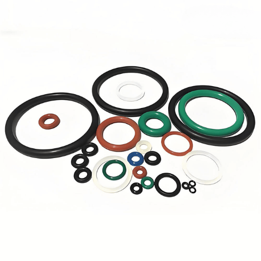
Una junta tórica se especifica mediante dos parámetros: diámetro interior (ID) y sección transversal (CS). Nunca se especifica por diámetro exterior. Existen dos estándares dimensionales globales y mezclarlos puede ser un shock para el profesional.
SAE AS568 es el estándar dimensional aeroespacial basado en pulgadas para juntas tóricas. Asigna a cada tamaño un número de guión «a -012 o -214, por ejemplo « y cubre diámetros interiores desde aproximadamente 0,029 « hasta 26 «. ISO 3601 es el estándar métrico de juntas tóricas, publicado en varias partes que cubren dimensiones, carcasas, calidad y diseño antiextrusión.
Aquí está la trampa: dado que SAE AS568 e ISO 3601 usan diferentes sistemas de medición con diferente nomenclatura, un número de guión AS568 no significa nada en el sistema ISO. Ordene un “-214” sin nombrar el estándar y podrá recibir un anillo que no se asiente en su glándula. Indique siempre tanto el estándar como el tamaño.
📐 Nota de ingeniería « Cómo medir una junta tórica
Para medir una junta tórica, mida el anillo relajado con un par de calibres de diámetro y un calibre de sección transversal o un micrómetro y registre el promedio de aproximadamente cinco muestras. No se recomienda medir el anillo estirado (los elastómeros tienden a deformarse isotrópicamente, encogiéndose en CS aparente e inflándose en diámetro aparente cuando se tensan, dando una lectura de tamaño falso). Anillos desconocidos, miden con frecuencia y promedian.
Esa diferencia es un punto que los profesionales destacan cuando los compradores endurecen demasiado las tolerancias en las piezas flexibles:
“Especificar ±0,001 en dimensiones no es realista para la mayoría de los procesos de fabricación de un sello flexible ”tu especificación es para el molde, no para la pieza”
Las juntas tóricas estándar generalmente se suministran con una dureza de 70 Shore A con una tolerancia de ±5. Para trabajos de reparación y mantenimiento, prácticos kits de juntas tóricas preclasifican los tamaños más comunes en una caja conveniente, ahorrando tiempo en el dimensionamiento. Cuando su tamaño no es estándar, se pueden crear herramientas personalizadas para brindar cualquier ID y CS que la aplicación necesite.
Aplicaciones de juntas tóricas estáticas versus dinámicas
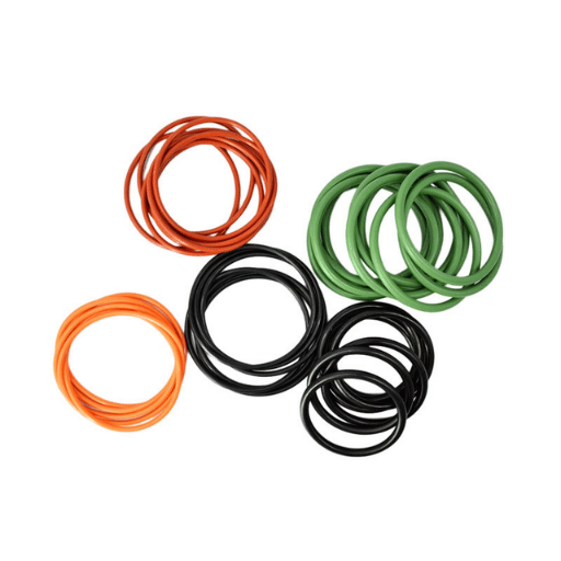
Etiquete la aplicación como estática o dinámica antes de seleccionar una junta tórica que afecte el diseño del apretón, la textura de la superficie, la dureza del material y el tipo de lubricación. Esa división estática versus dinámica es la división principal en el diseño de sellado después de la selección del material.
Un sello estático no implica ningún movimiento relativo entre la superficie de contacto (una cubierta atornillada, un puerto roscado, una brida de tubería). Mientras que en el sello dinámico implica movimiento: - un pistón alternativo en un cilindro hidráulico, un eje giratorio o un vástago de válvula oscilante.
✔ Aplicaciones estáticas
- Mayor tolerancia al apretón (20-30%)
- El acabado superficial Ra 16-32 µin es adecuado
- Se necesita lubricación mínima
- Más indulgente con la elección de materiales, incluida la silicona
⚠ Aplicaciones dinámicas
- Apretón inferior (reciprocante 10-20%, giratorio 0-10%)
- Se requieren superficies más lisas (Ra 8-16 µin)
- La lubricación continua es obligatoria
- Necesita compuestos resistentes a la abrasión, no silicona
El servicio dinámico es implacable porque cada ciclo lleva el sello. Una junta tórica alternativa en un actuador neumático puede sufrir millones de golpes; una junta tórica giratoria en un eje combate el calor de fricción todo el tiempo que funciona. Si se equivoca, el acabado de la superficie es demasiado rugoso y desgasta el anillo, demasiado liso (pulido con espejo) y no puede contener una película lubricante, y un sello dinámico falla temprano independientemente del material.
💡 Conclusión clave
Decida primero estático o dinámico. Todo lo que está aguas abajo 'apretar, terminar, dureza, lubricación - está establecido por esa única clasificación.
Modos comunes de falla de juntas tóricas y cómo detectarlos
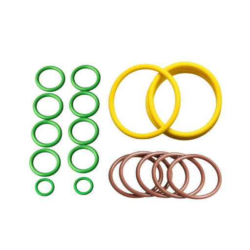
Una junta tórica fallida es un registro de diagnóstico. Su apariencia le indica la causa raíz y reemplazarla con un anillo idéntico sin leer ese registro garantiza una repetición de la falla. La mayoría de las fallas se remontan a una de tres fuerzas: medios incompatibles, temperatura fuera del rango nominal o tensión mecánica que el sello nunca fue diseñado para absorber. Aquí están los modos de falla que más ven los ingenieros y la firma visual de cada uno.
- Ajuste de compresión: el anillo está permanentemente aplanado en dos lados y no salta hacia atrás. Causado por sobrecompresión, exceso de calor o un material con mala recuperación. Uno de los fallos de las juntas tóricas citados con más frecuencia.
- Bordes irregulares y desconchados en el lado de baja presión, donde el anillo fue forzado a entrar en el espacio libre. Causado por alta presión más un espacio demasiado grande; la solución es un compuesto más duro o un anillo de respaldo antiextrusión.
- Descompresión explosiva: ampollas, divisiones o picaduras internas después de una rápida caída de presión. El gas absorbido por el elastómero se expande más rápido de lo que puede escapar. Crítico en el servicio de hidrógeno, CO2 y gas a alta presión.
- Degradación térmica: grietas en la superficie radial y una piel endurecida y brillante. Aquí el material se hizo correr por encima de su rango de temperatura.
- Hinchazón química o degradación, ablandamiento, ampollas o un cambio mensurable en tamaño y dureza. Aquí el elastómero es incompatible con el medio « una falla de compatibilidad química.
- Abrasión: una banda plana desgastada con finos rayones paralelos, solo en un lado. Un problema de sellado dinámico por superficies rugosas o pérdida de lubricación.
- Fallo en espiral: una espiral circunferencial cortada alrededor del anillo. Aquí el sello se retorcía en lugar de deslizarse durante un movimiento alternativo lento.
- Instalación de cortes o muescas que limpian los daños. Aquí el anillo se encontraba con un borde de ranura afilado o una rosca durante el montaje, a menudo porque se secaba.
¿una junta tórica detendrá una fuga?
Sí, siempre que el elastómero sea correcto, el tamaño sea correcto y el sello esté instalado correctamente en una ranura adecuada. Una junta tórica no puede evitar una fuga con una superficie de sellado rayada, o una ranura corroída o desgastada, o un elastómero que ya ha tomado un juego de compresión, o el material de junta incorrecto para el fluido o gas del proceso. A menudo ocurre que los peores infractores de fallas en las juntas tóricas no son los anillos, sino las superficies de contacto. Una fuga que regresa inmediatamente después de un cambio de junta tórica suele ser una superficie de contacto dañada, no un anillo defectuoso. Inspeccione la ranura y el eje antes de culpar al sello.
⚠¦ Error común
Tirar un anillo averiado sin investigarlo es el hábito más costoso en el mantenimiento de juntas tóricas. Un equipo de mantenimiento de una prensa hidráulica seguía instalando repetidamente anillos de nitrilo idénticos, que presentaban daños claros por extrusión cada vez. Causa raíz: limpieza desgastada de varilla y glándula, evidente a partir de una única inspección del anillo averiado. Pasaron meses de repetidas reparaciones antes de que se encontrara la causa.
Cómo seleccionar la junta tórica de goma adecuada: The PETS Check
La selección de juntas tóricas parece abrumadora para los recién llegados porque hay cientos de compuestos diferentes enumerados en los catálogos. En la práctica, el proceso de decisión es rápido: hay cuatro preguntas que vale la pena responder en orden, utilizando nuestro concepto de control PETS 'Presión, entorno, temperatura y tamaño/movimiento.
Las MASCOTAS verifican « cuatro preguntas según una especificación completa de junta tórica
- Presión P-Renunciante. ¿Qué tan alto es y es constante o cíclico? Baja presión: use un 70 Shore A estándar. Alta presión: opte por 90 Shore A y/o un anillo de respaldo antiextrusión.
- E -medio Ambiente. ¿Qué fluido o gas estará en contacto con el sello? Es mejor comprobarlo colocando el elastómero en una tabla de compatibilidad química; esta es la consideración más importante después de la presión.
- Temperatura T-R. ¿Cuál es la temperatura mínima y máxima de funcionamiento? (¡Y los transitorios también!) Selle los límites, no el medio.
- S --stance & movimiento. ¿Es un sello estático o dinámico en tamaños AS568 o ISO 3601? El movimiento influirá en la compresión, el acabado y la dureza.
Para utilizar estas cuatro preguntas, la mayoría de los fabricantes de equipos originales consideran que su elección de elastómero es bastante predecible. A continuación se muestra una tabla que muestra los resultados utilizando condiciones operativas típicas para determinar un material de partida ideal, seguida de una ilustración de cómo se puede refinar.
| Condición de servicio | Material de partida | Por qué |
|---|---|---|
| Ulei hidraulic, ≤100 °C | NBR (nitrilo) | Tamaño adecuado, menor costo, excelente resistencia al aceite |
| Combustible caliente o productos químicos, hasta 200 °C | FKM | Amplia resistencia química y térmica |
| Agua, vapor, líquido de frenos | EPDM | Resiste agua y fluidos polares; nunca lo use con aceite de petróleo |
| Alimenticio, médico, estática a altas temperaturas | Silicona | Inerte y tolerante a la temperatura; solo servicio estático |
| Productos químicos agresivos, calor extremo | FFKM | Resistencia casi universal; especifique sólo cuando esté justificado por el costo |
Un ejemplo ilustra la importancia de seguir el orden de los criterios de decisión. Un equipo de ingeniería especificó una junta tórica EPDM para instalarla en una caja de cambios pequeña porque se decía que “EPDM es resistente a la intemperie”. Al cabo de un mes, los sellos se habían hinchado y se habían ablandado: el hecho era que la caja de cambios estaba lubricada con aceite de petróleo, al que EPDM no puede resistir. Si hubieran aplicado el orden PETS a las especificaciones, habrían detectado este problema potencial de inmediato. Primero se aplican los parámetros de presión y ambiente, se eliminan todos los materiales incorrectos y luego la temperatura y el tamaño reducen lo posible a la elección final.
Cómo se fabrican las juntas tóricas de caucho: procesos de moldeo
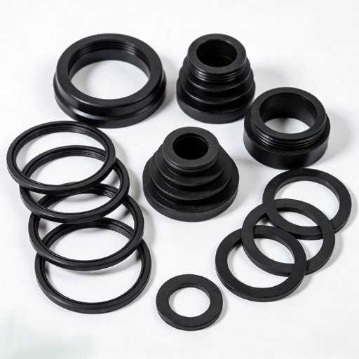
Las juntas tóricas se moldean curando (vulcanización) un elastómero sin curar en un molde calentado. Se utilizan tres procesos principales y la selección depende del costo de las herramientas, el volumen de producción y los requisitos de precisión.
- El moldeo por compresión del caucho sin curar se carga directamente en el espacio y luego se comprime. Costos mínimos de herramientas; adecuado para producción de bajo volumen y grandes secciones transversales. Requerirá recorte rápido.
- El compuesto de caucho sin curar para moldeo por transferencia se mueve desde una olla bajo calor a través de bebederos en una cavidad calentada hacia los bloques de molde. Costos de herramientas más altos pero mayor control dimensional que el moldeo por compresión.
- Moldeo por inyección «el caucho se calienta y se inyecta directamente en un molde cerrado. La inversión en herramientas es muy alta aquí, pero también lo son la precisión y el volumen de producción.
Dos realidades de fabricación son relevantes para el comprador. La calidad del curado no se puede ver, pero es fundamental: una junta tórica poco curada parece idéntica pero funciona mal en resistencia a la compresión y falla prematuramente en servicio. Una junta tórica AS568 disponible en el mercado satisfará la mayoría de los usos; elegir herramientas más elaboradas o personalizadas sólo es significativo si la ranura no es estándar, se requiere un compuesto específico o los altos volúmenes de producción hacen que el moldeo por inyección sea económico.
En los tres procesos, la referencia canónica para el diseño de ranuras y materiales sigue siendo el Manual de juntas tóricas de Parker Hannifin (ORD 5700).
Un fabricante de caucho que mezcla sus propios compuestos monitorea la receta de curado y la certificación del material de principio a fin. Engelhardt ejecuta nueve compuestos de elastómero internos y los tres procesos de moldeo bajo un mismo techo « ver su moldura de junta tórica de goma personalizada capacidades para tamaños no estándar y compuestos especiales.
La perspectiva de la junta tórica de caucho: lo que está cambiando en 2026
La tecnología de juntas tóricas está madura, pero tres fuerzas están remodelando la selección de materiales en este momento, y cada una tiene un impacto directo en la adquisición.
Regulación de PFAS y fluoroelastómeros. FKM y FFKM son fluoroelastómeros, una clase atrapada en la amplia propuesta de restricción de PFAS de la UE. El momento es concreto: la opinión del comité de evaluación de riesgos de la Agencia Europea de Productos Químicos deberá presentarse en 2026, con una opinión socioeconómica y cualquier restricción industrial gradual que se produzca hacia finales de la década.
Importante: esta es una fase de trabajo preliminar, no una prohibición (las asociaciones comerciales de la UE están presionando activamente para que se concedan exenciones para cubrir usos clave de sellado, y se espera que esas exenciones se concedan ampliamente). Si está planeando productos de próxima generación durante varios años, asista al Proceso PFAS de la ECHA, pero no vuelva a calificar el pánico en los sellos FKM en uso en 2026.
Energía de hidrógeno. La expansión del combustible y el almacenamiento de hidrógeno está aumentando la demanda de juntas tóricas que resistan la descompresión explosiva. Debido a que la molécula de hidrógeno es tan pequeña, se difunde fácilmente en elastómeros, por lo que los sellos de servicio de hidrógeno requieren cada vez más compuestos FKM y FFKM especialmente formulados en lugar de grados estándar.
Vehículos eléctricos. Las baterías de vehículos eléctricos y los sistemas de gestión térmica necesitan muchos sellos, pero también crean competencia: los selladores aplicados con líquido están desplazando algunas juntas tóricas discretas en las juntas de los paquetes de baterías. Donde quedan juntas tóricas, la tendencia es hacia compuestos de mayor temperatura adecuados para el calor de carga rápida.
El consejo práctico para 2026: continúe especificando el caucho de nitrilo donde se ajuste « Las reglas de PFAS no tienen relación con él, y sigue siendo el sello más rentable « y reserve el esfuerzo de recalificación de fluoroelastómeros para líneas de productos genuinamente expuestas a PFAS.
Preguntas frecuentes
¿cuáles son los dos tipos principales de juntas tóricas?
Ver respuesta
Por función, existen aplicaciones estáticas y dinámicas. En una aplicación estática, las superficies de contacto de los componentes son estacionarias. En una aplicación dinámica, las superficies de contacto se mueven hacia adelante y hacia atrás, girando u oscilando.
Esta organización determina el apretón, el acabado de la superficie y el material mucho antes de seleccionar un tamaño.
¿cuál es el propósito de una junta tórica?
Ver respuesta
Junta tórica: Para sellar el paso de un fluido o gas entre dos partes de una junta mecánica. Normalmente se coloca en una ranura y se comprime entre dos partes, luego se deforma para llenar el espacio y, a medida que aumenta la presión del sistema, se sella más a medida que aumenta la carga.
¿cómo identifico el material de una junta tórica desconocida?
Ver respuesta
La selección de elastómeros no es trivial: el color por sí solo puede ser negro NBR, FKM o EPDM. Utilice el contexto como primera guía: el aceite de petróleo indica nitrilo, agua o líquido de frenos significa EPDM, la temperatura alta apunta a FKM o silicona. Para clarificar y garantizar el material, analice una muestra, no adivine.
¿se puede reutilizar una junta tórica de goma?
Ver respuesta
No es habitual. Después de usar la junta tórica OE, ya ha experimentado cierta compresión y la reinstalación inmediata puede causar fallas y fugas. Cuando no se trata de costos elevados, es normal cambiar las juntas tóricas en cada intervalo de servicio.
¿se siguen utilizando juntas tóricas de caucho en la ingeniería moderna?
Ver respuesta
Absolutamente. Las juntas tóricas son el sello predeterminado en todas las formas de hidráulica, desde usos automotrices y aeroespaciales, y en equipos de proceso. Los selladores líquidos están ganando algo de tracción en aplicaciones de alto valor como los paquetes de baterías para vehículos eléctricos, pero en general, la versatilidad y el bajo costo de la junta tórica dominan el día.
¿qué lubricante se debe utilizar en las juntas tóricas?
Ver respuesta
Seleccione un lubricante compatible tanto con el elastómero como con medios. Generalmente se aplican grasas de silicona, pero verifique la dureza, la compatibilidad de los medios y la temperatura de los medios para cada caso de uso. Lubrique el sello para la instalación y operación dinámica, y verifique la compatibilidad de los medios.
¿Cuánta presión puede soportar una junta tórica de goma?
Ver respuesta
Una junta tórica correctamente diseñada sella miles de psi. Lo que limita no es el elastómero sino el espacio libre: a medida que aumenta la presión, el anillo intenta extruirse en ese espacio. Los diseños de alta presión utilizan compuestos rígidos 90 Shore A y anillos de respaldo antiextrusión.
¿necesita un tamaño de junta tórica específico fuera del catálogo normal (compuesto, diámetros o dimensiones especiales)...?
Consulte Moldeo de juntas tóricas personalizado →
Obtenga el resumen de capacidad
Acerca de esta guía de juntas tóricas
Esta guía combina datos de material, tamaño y falla de juntas tóricas de estándares preexistentes (SAE AS568, ISO 3601, ASTM D2000 y D1414) y el conocimiento del equipo de ingeniería de caucho y silicona Engelhardt, que ha fabricado juntas tóricas moldeadas personalizadas y elastómeros. sellos desde 2009. Los rangos de diseño, como los porcentajes de compresión y la rugosidad de la superficie, son valores típicos (para verificar las especificaciones de glándulas y materiales para el medio y el sello en particular antes de la producción).
Referencias y fuentes
- SAE AS568 « Tamaño Aeroespacial Estándar para Juntas Tóricas « SAE International
- ISO 3601-1 « Sistemas de energía fluida, juntas tóricas: diámetros interiores, secciones transversales, tolerancias « Organizare internațională pentru standardizare
- ASTM D2000 « Sistema de clasificación estándar para productos de caucho en aplicaciones automotrices « ASTM International
- ASTM D1414 “Métodos de prueba estándar para juntas tóricas de caucho « ASTM International
- Informe de la Comisión Presidencial sobre el accidente del transbordador espacial Challenger -nasa
- Sustancias perfluoroalquiladas y polifluoroalquiladas (PFAS) «proceso de restricción « Agenția Europeană de Chemicals
Recursos relacionados
- Juntas tóricas personalizadas de caucho y silicona « tamaños no estándar y compuestos elastómeros especiales
- Moldeo por compresión de caucho ñafácil para composiciones que mejor se adaptan a la ductilidad, producción a granel
- Moldeo por inyección de caucho -producción de alta precisión y gran volumen
- Moldeo por transferencia de caucho ñan alternativa de costo moderado con menor variabilidad dimensional
- Capacidades personalizadas de moldeo de caucho « descripción general completa de la fabricación de elastómeros