Póngase en contacto con Engelhardt


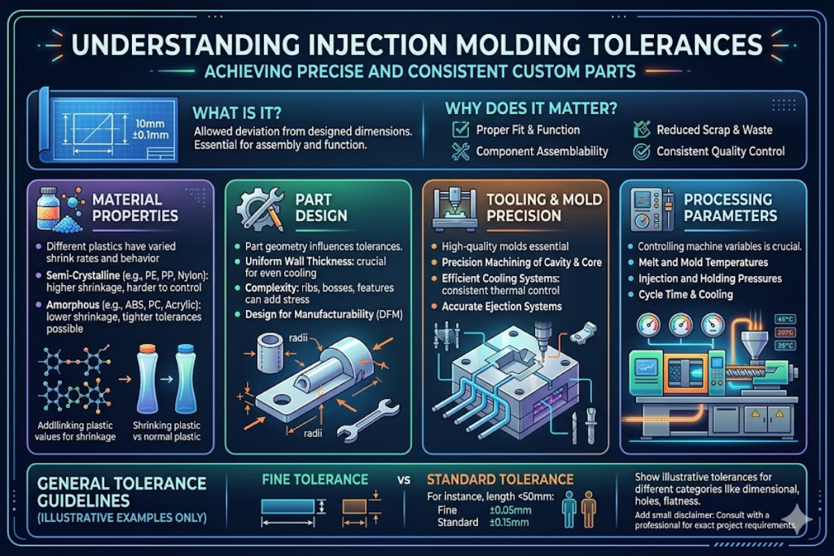
Las tolerancias de moldeo por inyección definen la variación dimensional aceptable en una pieza moldeada, expresada como ±mm (o ±in) frente a las dimensiones nominales. Elegir la banda de tolerancia correcta distingue una pieza que se ajusta por primera vez de una que cuesta dos revisiones de molde y tres validaciones de proceso para enviar. Esta guía cubre las tres referencias reales de los ingenieros de estándares de la industria (SPI, DIN 16742, ISO 20457), cómo calcular los presupuestos de tolerancia frente a la contracción específica del material y las prácticas DFM que permiten que las piezas moldeadas por inyección tengan ±0,025 mm sin triplicar el costo unitario.
Especificaciones rápidas: Bandas de tolerancia al moldeo por inyección
| Comercial (estándar) | ±0,125 mm / ±0,005 in « costo base 1,0× |
| Fino/Medio | ±0,075 mm / ±0,003 in « 1,7× costo |
| Precisión | ±0,025 mm / ±0,001 in « 3,0× costo |
| Normas aplicables | SPI (EE. UU.), DIN 16742 TG1-TG9, ISO 20457:2018 |
| Factor dominante | Contracción del material (0,3% ABS a 3,5% POM) |
| Regla de espesor de pared | Variación ≤ 10% para piezas de tolerancia estricta |
¿qué son las tolerancias al moldeo por inyección?
Una tolerancia de moldeo por inyección es la desviación permitida de una dimensión nominal en un componente moldeado. Por ejemplo, si un saliente se especifica como 10,00 ±0,05 mm, cualquier medida entre 9,95 mm y 10,05 mm pasa la inspección. Existen tolerancias porque las piezas moldeadas por inyección no se pueden producir con variación cero “contracción, ciclos térmicos, desgaste del molde y deriva del proceso introducen una desviación del modelo CAD.
Los diseñadores suelen especificar tolerancias en tres bandas. La tolerancia comercial de ±0,125 mm cubre la mayoría de las piezas industriales y de consumo que no necesitan encajar con precisión. La tolerancia fina de ±0,075 mm se aplica a superficies de contacto, ajustes rápidos y características que deben deslizarse o girar contra otra pieza. La tolerancia de precisión de ±0,025 mm está reservada para ajustes de cojinetes, superficies de sellado, alineación óptica y geometrías de dispositivos médicos. Entre Fina y Precisión, se puede lograr una tolerancia de ±0,05 mm en dimensiones inferiores a 100 mm con una herramienta debidamente especificada y un proceso validado.
La penalización de costos aumenta de forma no lineal con precisión. Cada paso hacia abajo en la banda de tolerancia exige un mecanizado de herramientas más estricto, tiempos de ciclo más largos, una validación del proceso más extensa o una combinación de los tres, y los incrementos compuestos.
Los 4 tipos de tolerancias en el moldeo por inyección
Los dibujos de piezas moldeadas por inyección utilizan cuatro categorías de tolerancia distintas, cada una de las cuales controla un aspecto diferente de la geometría de la pieza. Combinarlos es la razón más común por la que un dibujo pasa la revisión pero falla la inspección del primer artículo.
- Tolerancias dimensionales “desviaciones lineales y angulares frente a valores nominales. Expresado como ±mm o como dimensiones límite (10,00/9,95 mm). Esto es lo que la mayoría de los diseñadores consideran ”tolerancia”.
- Tolerancias geométricas ^ controles de forma y orientación del marco GD&T: planitud, rectitud, circularidad, cilindro, perpendicularidad, paralelismo, angularidad. Una cara plana puede pasar todas las comprobaciones dimensionales y aun así fallar si se inclina bajo expulsión.
- Tolerancias posicionales « ubicación de la característica relativa a los marcos de referencia de referencia. Los patrones de orificios para la alineación de sujetadores son el caso clásico; La tolerancia posicional de ±0,1 mm evita una deriva acumulada entre datos y características.
- Tolerancias de forma « warpage, marcas de hundimiento y desviaciones impulsadas por la contracción que distorsionan toda la pieza en lugar de las características individuales. Estos son los más difíciles de controlar porque surgen de la física refrescante.
Las especificaciones completas abordan las cuatro categorías. Los dibujos que solo muestran ±mm en dimensiones lineales dejan que el moldeador adivine la planitud y la posición, que es donde se originan la mayoría de las disputas de tolerancia.
Estándares de la industria: SPI, DIN 16742 e ISO 20457
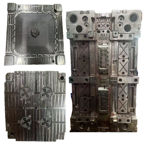
Tres estándares establecen el lenguaje de tolerancia común en todos los procesos de fabricación de piezas moldeadas por inyección. No son intercambiables: elija el que espera su mercado final y su base de clientes.
Estándares de tolerancia SPI (Estados Unidos)
Los estándares de tolerancia SPI se originaron en la Sociedad de la Industria del Plástico, ahora la Asociación de la Industria del Plástico (PLÁSTICOS). SPI especifica tablas de tolerancia comercial y fina indexadas por rango de dimensiones, con precisión agregada por la práctica moderna de la industria. SPI es el valor predeterminado en los dibujos de moldeo por inyección de dispositivos médicos, electrónicos de consumo y automotrices de América del Norte.
DIN 16742: Nueve grupos de tolerancia con metodología de evaluación puntual
DIN 16742:2013 “Piezas moldeadas de plástico ”Tolerancias y condiciones de aceptación” define nueve grupos de tolerancia, TG1 a TG9, indexados a rangos de tamaño nominal. TG1 cubre dimensiones de ultraprecisión « de 1 a 3 mm, TG1 especifica ±0,007 mm, que es el territorio de los componentes ópticos y de microfluidos. TG5 a TG7 cubren la mayor parte del moldeo por inyección comercial y de tolerancia fina, con TG7 a ±0,037 mm en el rango de 1 a 3 mm.
DIN 16742 se distingue por su esquema de evaluación de puntos: cinco influencias de producción (comportamiento de contracción del material, complejidad del molde, tamaño del lote, estabilidad del proceso, operaciones posteriores al molde) obtienen cada una una puntuación y la suma se asigna a la clase TG aplicable. Esto evita que los dibujos especifiquen tolerancias poco realistas sin herramientas ni inversión en procesos a la altura.
ISO 20457:2018 « Punto de referencia internacional
ISO 20457:2018 “Piezas moldeadas de plástico ”Tolerancias y condiciones de aceptación’ es el estándar internacional armonizado con los grados de tolerancia de TI ISO 286-1 (IT01 a IT18). Extiende la lógica de DIN 16742 a un marco global y es la referencia preferida para las cadenas de suministro multinacionales. Engelhardt's capacidades de moldeo por inyección de precisión están especificados según ISO 20457 para clientes internacionales y de la UE.
Tabla de tolerancia al moldeo por inyección por rango de dimensiones
Escala de bandas de tolerancia con dimensión nominal. Es factible una tolerancia de ±0,05 mm en una característica de 10 mm; en una característica de 200 mm, cruza hacia territorio de subprecisión y requiere procesos de micromoldeo. La siguiente tabla resume las tolerancias alcanzables por clase y rango de dimensiones, según la referencia cruzada de SPI y DIN 16742.
| Dimensiones Rango | Comercial (±mm) | Fino (±mm) | Precisión (±mm) |
|---|---|---|---|
| 0 ñan 25 mm | ±0,100 | ±0,050 | ±0,025 |
| 25 ñan 50 mm | ±0,125 | ±0,075 | ±0,035 |
| 50 ñan 100 mm | ±0,175 | ±0,100 | ±0,050 |
| 100 ñan 200 mm | ±0,250 | ±0,150 | ±0,075 |
| > 200 mm | ±0,1% de tenue | ±0,05% de tenue | Caso por caso |
Como guía aproximada, presupueste aproximadamente 0,5% de la dimensión nominal para comercial, 0,2% para fino y 0,1% para precisión, en todas las dimensiones superiores a 25 mm. La línea guía porcentual no es un sustituto de las tablas de estándares, pero es útil para la revisión DFM de primer paso.
Factores que afectan la tolerancia: contracción del material, herramientas y procesos
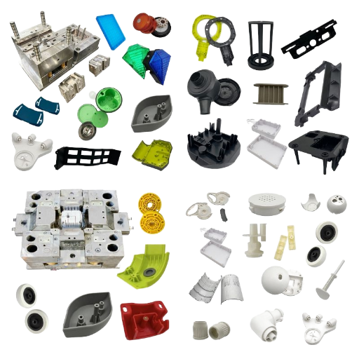
Tres factores determinan si es factible un paso de tolerancia. Domina la contracción del material. El diseño de la herramienta lo permite. Los parámetros del proceso se estabilizan.
Contracción del material por resina
Cada resina de moldeo por inyección se encoge a medida que se enfría desde la temperatura de fusión hasta la temperatura ambiente. La velocidad de contracción depende de la cristalinidad de la resina, el refuerzo de la fibra y la química de los aditivos. Las resinas amorfas se enfrían hasta alcanzar una estabilidad dimensional más precisa; Las resinas semicristalinas tienden a contraerse direccionalmente.
| Resina | Tasa de contracción | Comportamiento |
|---|---|---|
| ABS | 0.3 – 0.8% | Amorfo, uniforme, predecible |
| Policarbonato (PC) | 0.5 – 0.8% | Amorfo, muy consistente |
| Polipropileno (PP) | 1.0 – 2.5% | Semicristalino, anisotrópico |
| PA66 (nylon sin rellenar) | 0.8 – 1.5% | Semicristalino, sensible a la humedad |
| PA66 con fibra de vidrio 30% | 0.1 – 0.8% | El refuerzo reduce la contracción y aumenta la anisotropía de la urdimbre |
| POM (acetal, copolímero) | 1.5 – 3.5% | Mayor contracción entre las resinas de ingeniería de productos básicos |
| MIRAR | 1.0 – 1.5% | Semicristalino, requiere un estricto control del proceso |
Diseño y Construcción de Herramientas
Los moldes de inyección mecanizados CNC normalmente miden de 0,005 a 0,010 mm en la cavidad y el núcleo. Esta precisión de mecanizado establece el límite inferior para la tolerancia final de la pieza moldeada por inyección, ya que no se puede inyectar el molde más apretado de lo que permite la herramienta. La colocación de los pasadores del eyector, la ubicación de la línea de enfriamiento y la ubicación de las compuertas influyen en la contracción diferencial. Las compuertas compensadas producen un flujo asimétrico, lo que provoca una contracción asimétrica, y cualquiera que sea la forma en que establezca las condiciones posteriores, el proceso exacerbará el desequilibrio para evitar la deformación diferencial.
Parámetros del proceso
La presión de inyección, la presión de retención, el tiempo de retención, la temperatura del molde, la temperatura de fusión y el tiempo de enfriamiento inducen y están influenciados por las diminutas diferencias entre partes. Hoy en día, con sensores en molde y controles de circuito cerrado, la variación en un ciclo parcial se reduce a, digamos, 0,01 mm, pero ese es sólo el caso con condiciones apropiadas de molde, resina y ventana de proceso.
📐 Nota de Ingeniería « Compensación de Contracción en CAD
Los diseñadores de herramientas aplican un factor de escala de 1,005 a 1,020 (dependiendo de la resina) a las dimensiones de la cavidad para tener en cuenta la contracción por enfriamiento. Si se utiliza el factor incorrecto, esta será la causa más común de errores de dimensión de la primera parte de la prueba. Especifique la resina objetivo al inicio del diseño de la herramienta y vuelva a ejecutar la escala de contracción si la resina cambia en el curso del proyecto.
Mejores Prácticas y Diseño para la Fabricabilidad (DFM)
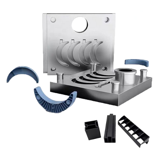
El diseño para la fabricabilidad (DFM) para piezas moldeadas por inyección de alta precisión no requiere muchos “¿qué trucos?” más bien requiere una práctica de dibujo disciplinada. A continuación se muestran ocho prácticas que a menudo vemos omitidas entre comillas para moldes de inyección de tolerancia estricta.
Lista de verificación DFM para piezas moldeadas por inyección de tolerancia estricta
- Mantenga la variación del espesor de la pared del núcleo y la cavidad dentro de 10% del espesor total de la pared. El enfriamiento diferencial es la principal fuente de deformación.
- Especifique tolerancias estrictas solo en las características de acoplamiento (puntos de sellado, ajustes de cojinetes, etc.), deje todo lo demás en un grado comercial.
- Utilice datos de referencia ASME Y14.5 o referencias del eje ISO 1101 en todas las características críticas.
- Especifique el factor de escala de contracción preciso en CAD al inicio de un proyecto, correspondiente a la resina objetivo.
- Diseño para geometría simétrica siempre que sea posible para minimizar la deformación causada por el enfriamiento asimétrico.
- Especifique las nervaduras (60% del espesor de la pared principal) si se debe aumentar el espesor, no el espesor de la pared principal.
- Ubique las puertas lejos de dimensiones críticas y características de ajuste a presión
- Cree análisis de acumulación de tolerancia en ensamblajes antes de congelar el dibujo.
📐 Nota de ingeniería « Muestras T1 e informes dimensionales del primer artículo
Las muestras T1 (prueba de herramientas 1) nunca llegarán a dibujos ajustados en la primera toma. Planifique al menos dos iteraciones (T1 y T2) con informes dimensionales y prepárese para una tercera (T3) y única ejecución de desarrollo de proceso dedicada si se requieren tolerancias estrictas.
La revisión de DFM de proveedores es la intervención de mayor impacto disponible para piezas de tolerancia estricta. Engelhardt servicios de moldeo por inyección de plástico incluya la revisión de DFM según los ocho criterios anteriores como parte de cada cotización, no como un cargo de ingeniería separado.
Impacto en los costos de las tolerancias estrictas
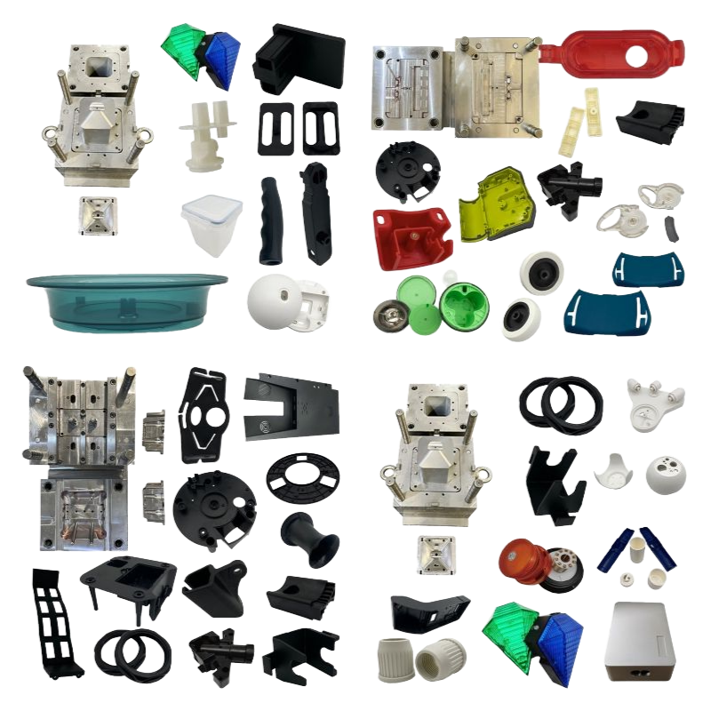
Una determinada clase de tolerancia influye en el tiempo del molde y del ciclo, así como en la complejidad de la inspección. Los multiplicadores de costos no son lineales; pueden ser aditivos.
| Clase de tolerancia | Multiplicador de costos | Conductores primarios |
|---|---|---|
| Comercial (±0,125 mm) | 1,0× basal | Herramienta estándar, ciclo estándar |
| Fino/Medio (±0,075 mm) | 1.7× | Mecanizado de herramientas más ajustado, ciclos más largos, inspección de muestras |
| Precisión (±0,025 mm) | 3.0× | Construcción de herramientas de precisión, sensores en molde, validación DOE extendida |
| Subprecisión (< ±0,025 mm) | 3,5× și sus | Micromoldeo, proceso dedicado, inspección dimensional 100% |
Una matriz de decisión simple: especifique apretado sólo cuando la función lo justifique. Utilice una tolerancia estricta cuando proteja las ranuras del sello, proporcione ajuste del rodamiento, asegure la claridad óptica y permita el ajuste a presión. No especifique apretado justo donde existen bordes cosméticos o protuberancias en los hombros; no justifican el costo.
Errores comunes: sobreespecificación, acumulación de tolerancia y suposiciones materiales
Hay tres errores de dibujo críticos que causan la mayor cantidad de disputas de tolerancia. Todos son costosos y también se pueden prevenir con prácticas de dibujo disciplinadas, como se documenta en las ocho prácticas anteriores.
✔ Ce să face
- Aplique una tolerancia estricta sólo a las funciones funcionales
- Ejecute RSS o análisis de pila del peor de los casos en ensamblajes
- Utilice valores de contracción específicos del material en CAD
- Especifique los marcos de referencia de referencia por GD&T
⚠¦ Qué evitar
- Manta ±0,025 mm en todo el dibujo
- Suponiendo pila de ensamblaje = suma de tolerancias individuales
- Usando una contracción genérica de 0,5% para cada resina
- Tolerancias de congelación antes de la revisión del DFM
⚠¦ Tres errores que impulsan las disputas de tolerancia
- Sobreespecificación de tolerancias en superficies no funcionales. Aplicar ±0,025 mm en todo el dibujo en lugar de solo las características de acoplamiento aumenta de 2 a 3 veces sin brindar un beneficio funcional. Los moldeadores experimentados informan constantemente que este es el hábito de dibujo más caro.
- Ignorando la pila de tolerancia en los ensamblajes. Cinco partes cada una a ±0,1 mm se acumulan hasta ±0,5 mm en el peor de los casos, o aproximadamente ±0,22 mm usando la suma raíz cuadrada. Los diseños que suponen que la tolerancia de una pieza individual es igual a la tolerancia del ensamblaje no pasan la inspección final incluso cuando cada pieza pasa las comprobaciones individuales.
- Uso de valores de contracción genéricos para resinas especiales. La especificación de un factor de contracción de 0,5% para nailon relleno de vidrio de 30% (realmente de 0,1 a 0,8%) produce piezas de tamaño insuficiente. Utilice siempre la hoja de datos del fabricante de resina, no un promedio de materiales cruzados.
Preguntas frecuentes
¿cuáles son las tolerancias típicas para el moldeo por inyección?
Ver respuesta
La tolerancia comercial es de 0,125 mm, la tolerancia fina es de 0,075 mm y la tolerancia de precisión es de 0,025 mm. Estos valores alcanzables dependen del rango de dimensiones, la contracción del material y las protuberancias de 10 mm de geometría de la dimensión tienen una tolerancia más estricta que las caras de 200 mm.
¿cuál es la tolerancia a 0,05 en el moldeo por inyección?
Ver respuesta
Las tolerancias de 0,05 mm se establecen en el borde entre las clases SPI Fine y Precision. Estas tolerancias se pueden colocar en dimensiones inferiores a 100 mm cuando se gestionan direccionalmente con una herramienta correctamente especificada y un proceso aprobado, normalmente entre 1,3 y 1,8 del coste comercial de referencia.
¿cuál es la norma ISO para tolerancias de moldeo por inyección?
Ver respuesta
ISO 20457:2018 “Piezas moldeadas de plástico ñan Tolerancias y condiciones de aceptación” es el estándar internacional predominante. Adopta los grados de tolerancia de TI de ISO 286-1 (IT01 a IT18) y es el estándar al que se hace referencia con mayor frecuencia cuando se compra en una cadena de suministro multinacional. DIN 16742 es la norma alemana más citada e incluye los nueve grupos de tolerancia TG1 a TG9.
¿Cuáles son los 4 tipos de tolerancias?
Ver respuesta
Dimensional (desviaciones lineales y angulares), geométrica (controles de forma y orientación como planitud, perpendicularidad, concentricidad), posicional (ubicación de características en relación con los marcos de referencia) y tolerancias de forma (deformación, marcas de hundimiento, distorsión impulsada por la contracción). Un dibujo completo aborda las cuatro categorías.
¿Cómo afecta el espesor de la pared a la tolerancia?
Ver respuesta
Las secciones de pared más gruesas se enfrían más gradualmente y se encogen más. El desajuste excesivo de los espesores de las secciones de pared da como resultado una contracción diferencial, lo que provoca una deformación que evita aún más tolerancias estrictas. Como regla general, asegure la deformación y todas las tolerancias más estrictas que las comerciales, manteniendo al mismo tiempo una variación de 10% en el espesor de la pared.
¿por qué es importante la selección de materiales para calcular la contracción?
Ver respuesta
Las resinas tienen una contracción muy diferente: POM de 1,5 a 3,5% versus ABS de 0,3 a 0,8% constituye casi una diferencia de orden de magnitud. Los grados rellenos de vidrio reducen la contracción del orden de 0,1 a 0,8%, pero crean un comportamiento dimensional anisotrópico a lo largo del eje de flujo de la fibra. No establecer el factor de contracción correcto en el diseño de la herramienta es la razón número uno de las fallas de dimensión T1.
¿qué se considera una “tolerancia estricta” en el moldeo por inyección?
Ver respuesta
En la práctica, el trabajo de “tolerancia estricta” significa mantenerse en la clase SPI Precision o mejor (alrededor de ±0,025 mm en dimensiones críticas) en lugar de los ±0,125 mm típicos de la tolerancia de grado comercial. Requiere herramientas endurecidas y cortadas con precisión, un control más estricto de la ventana de proceso (temperatura de fusión, presión del paquete, temperatura del molde) y comprobaciones dimensionales durante el proceso, lo que normalmente eleva el costo de las herramientas y el tiempo del ciclo por encima de una pieza de tolerancia comercial. Especifíquelo sólo cuando la función realmente lo requiera, como interfaces de sellado, ajustes a presión o piezas que deben acoplarse con otros componentes de tolerancia estrecha en el ensamblaje.
¿necesita moldeo por inyección de precisión?
Envíenos su dibujo con las tolerancias objetivo, el material y el volumen de producción. Nuestra revisión de DFM confirmará la viabilidad frente a SPI, DIN 16742 e ISO 20457 antes del corte de herramientas.
Artículos relacionados
- Servicios de moldeo por inyección de plástico: descripción general de capacidades y materiales
- Moldeo por compresión versus moldeo por inyección: qué proceso se adapta a su pieza
- Diseño para la fabricabilidad de piezas moldeadas por inyección de plástico
- Guía de selección de materiales para piezas moldeadas por inyección
Referencias y fuentes
- ISO 20457:2018 « Piezas moldeadas de plástico: tolerancias y condiciones de aceptación « Organizare internațională pentru standardizare
- Asociación de la Industria del Plástico (PLÁSTICOS) « custodio de los estándares de tolerancia SPI
- ASTM D955 “Método de prueba estándar para medir la contracción de las dimensiones del molde de termoplásticos « ASTM International
- NIST/SEMATECH e-Handbook of Statistical Methods « Análisis de tolerancia « Instituto Nacional de Estándares y Tecnología de EE. UU
- ASME Y14.5 « Dimensionamiento y Tolerancia (GD&T) «Sociedad Americana de Ingenieros Mecánicos
Acerca de este análisis
Esta guía sintetiza los estándares de tolerancia SPI, DIN 16742 e ISO 20457 con datos de contracción de materiales de múltiples hojas de datos de fabricantes de resina, vigentes a abril de 2026. Los valores de tolerancia en los gráficos representan rangos típicos de la industria en lugar de reproducciones textuales de cualquier estándar único «estándar específico. Las tablas están disponibles en los organismos emisores. Para un proyecto de moldeo por inyección citado, la tolerancia final alcanzable depende de la resina específica, la construcción de la herramienta y la validación del proceso; Solicite una revisión de Engelhardt DFM con su dibujo de destino para obtener una respuesta específica del proyecto.