Treten Sie mit Engelhardt in Kontakt


Was Konstrukteure vor dem Sperren von Geometrie wissen müssen, müssen Entscheidungsregeln der ersten Partei und einer Klasse 7 1 TP15 T-Zelle wissen, die 1.000+ Tonnen pro Jahr produziert.
Diese 1TP15 T-Designrichtlinien beantworten die Fragen, die wichtig sind, bevor ein einzelner Formhohlraum geschnitten wird: wie dünn eine Wand ohne Porosität sein kann, wie viel Schrumpfung zu erwarten ist, nachdem das Teil die Presse verlässt, wann der Luftzug nicht verhandelbar ist und wann er übersprungen werden kann, und wo ein Blitz entsteht, wenn die Trennlinie an der falschen Stelle landet Flüssiger Silikonkautschuk verhält sich nicht so wie die Thermoplaste, die die meisten Produktdesigner zuerst lernen, und das Tragen thermoplastischer Instinkte in ein 1TP15 T-Programm ist der teuerste Fehler, den wir im Prototypenstadium sehen.
Auf einen Blick: LSR Design-Spezifikationen
Vor der Durcharbeitung der einzelnen Abschnitte bündelt diese Quick Specs Karte die acht Zahlen, die von mechanischen und Produktdesignern am häufigsten gefragt werden, die ein 1TP15 T-Programm starten Verwenden Sie sie zum schnellen Nachschlagen; die vollständige Argumentation lebt in den H2-Abschnitten unten.
Schnelle Spezifikationen, LSR-Formdesign
| Mindestwandstärke | 0,0,0 Zoll (0,254 mm) machbar mit Durchflussbilanz |
| Regel der Rippendicke | 0,5 –1,0 × angrenzende Wandstärke |
| Standard-Zugwinkel | 1° üblich; 0,5° vertikale Flächen; 3°+ für strukturierte Oberflächen |
| Erreichbare Toleranz | ±0,025 (1 TP2 T Boden) / ±0,08 mm typisch |
| Nachhärtende Schwindung | 2.5 – 31 TP20 T während der Kühlung + 0,5 – 0,71 TP20 T nach der Aushärtung |
| Blitzschwelle | Formspalten 1 0,0002 Zoll (0,005 mm) Leck |
| Zykluszeitband | 30 – 90 Sek. (1 TP2T 250 T-Zelle, 16-Hohlraum-Basislinie 45 –55 Sek.) |
| Werkzeugvorlaufzeit | 30 – 50 Tage neue Form; 40 SS-Produktionswerkzeug, 21-Meter-Zyklen |
Materialauswahl: Durometer, Grade und Zusatzstoffe
Materialentscheidungen kommen vor Geometrieentscheidungen in einem funktionierenden 1TP15 T-Programm Durometer Wanddurchführbarkeit, Gate s, und Entformungsverhalten (Pick den falschen Shore-Wert zuerst, und Sie das Teil neu gestalten später.
1TP15 T ist ein zweiteiliger, durch Zugabe gehärteter (platinkatalysierter) Duroplast, der kalt in eine beheizte Form eingespritzt wird, wo er irreversibel vernetzt Standard-Handels-Durometer deckt 30, 40, 50, 60 und 70 Shore A. Engelhardts ab Kundenspezifische 1TP15 T Spritzgussdienste Halten Sie eine breitere 5-Zeilen-Shore-A-Reihe mit einer jährlichen Produktion von 1.000+ Tonnen bereit, wobei die unteren Durometer-Sorten für Softdichtungen und die oberen Enden für Industriedichtungen reserviert sind.
Für medizinische Anwendungen ist die Shore-Auswahl nur der Anfang Materialnoten verzweigen sich in vier Arbeitskategorien, die jeweils an einen anderen Qualifizierungsweg gebunden sind:
- Standard LSR Industriedichtungen, Dichtungen, Konsumgüter Keine Dokumentation zur Vereinbarkeit erforderlich.
- Medizinisch-Grade LSR trifft 1 1TP10 T Biokompatibilitätsbewertung gemäß ISO 10993 und oft USP Klasse VI. In der Regel auch unter ISO 13485 produziert.
- Optisch-gradige LSR für Linsen, Lichtrohre, durchscheinende Gehäuse; erfordert kontrollierte Sauberkeit während der Verarbeitung.
- Fluorkieselsäure – Kraftstoff- und Ölbeständigkeit; geringere Dehnung, höhere Kosten.
Implantierbare Geräte Dimension. 1TP10 T-Leitlinie unterscheidet die kurzfristige Implantation (29 Tage hinzufügen) von der langfristigen Implantation (>29 Tage oder dauerhaft), und das Testprofil eskaliert entsprechend Ein von Experten begutachteter Review aus dem Jahr 2024 am Fortschritte bei der Charakterisierung von Silikonimplantaten Dokumentiert, wie Wirt-Gewebe-Interaktionen mit Oberflächenvorbereitung, Durometer und Füllstoffen variieren, und erinnert daran, dass “medizinische Qualität”ein Ausgangspunkt und keine Garantie ist.
💡 Drei-Fragen-Material vor dem Flug
Beantworten Sie vor dem Öffnen eines CAD-Modells diese drei Fragen:
- Welche Dauerbetriebstemperatur sieht das Teil? (Bestimmt, ob Standard-1TP15 T oder Fluorsilikon benötigt wird.)
- Welche Sterilisationsmethode gilt für Autoklaven, EtO, oder keine? (begrenzt nicht kompatible Qualitäten)
- Gibt es Patientenkontakt und wie lange? ( Legt den Umfang der Tests nach ISO 10993 / USP-Klasse VI fest.)
Das frühzeitige Sperren dieser drei Fragen verhindert die meisten regulierungsgetriebenen Neugestaltungen Verwenden Sie die 1TP15 T Materialauswahlrechner Antworten auf eine Startnote abzubilden.
Wandstärke, Rippen und Abschnittsübergänge
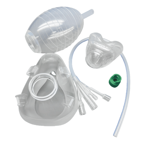
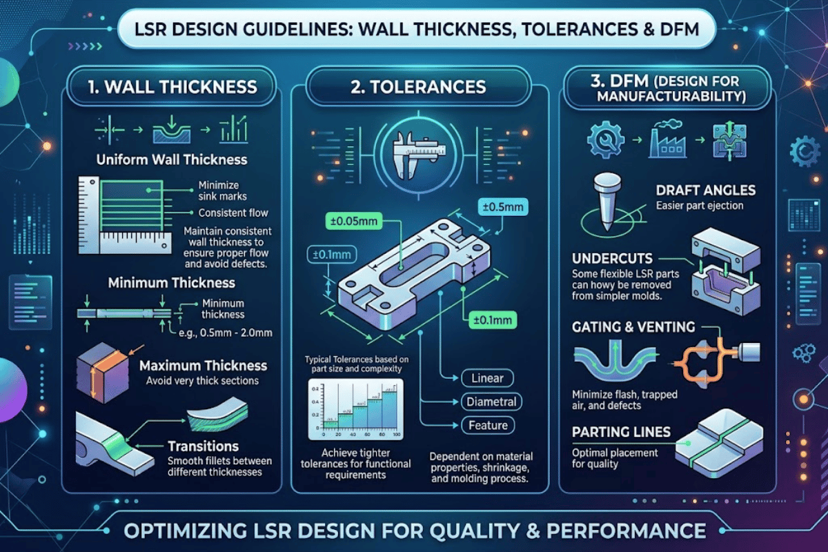
Die Wandstärke treibt fast alle nachgelagerten Kosten an: Hohlraumzahl, Zykluszeit, Strömungsbilanz und die Abstoßungsrate aufgrund der Porosität. Der veröffentlichte Industrieboden liegt bei 0,010 Zoll (0,254 mm), aber die Behandlung dieser Zahl als gelegentliches Minimum ist ein Rezept für Probeschmerzen.
Wie dünn können 1TP15 T Wände sein?
1TP15 T-Injektion kann Wände bis zu 0,010 Zoll (0,254 mm) füllen, und spezielle Programme erreichen darunter. Wackers ELASTOSIL LR-Verarbeitungshandbuch Beschreibt das platinkatalysierte Härtungssystem, das Dünnschliffströmungen praktisch macht, wobei die Viskosität unter Scherung im Läufer und Tor sinkt. Die praktische Bodentiefe hängt von drei Dingen ab: der Größe des dünnen Bereichs, der Lage benachbarter dickerer Abschnitte und wie aggressiv der Hohlraum entlüftet wird.
“Unsere 150-Tonnen-LSR-Presse füllt routinemäßig 0,020-Zoll-Wände mit Werkzeugen mit 64 Kavitäten. Unterhalb von 0,015 Zoll führen wir im Prototyp einen Durchflussausgleichsversuch durch, bevor wir uns auf den Hohlraum festlegen.”Dieses Probetraining über eine Woche mit Pressezeitkosten, das trivial mit einem 64-Zoll-Werkzeug verglichen wird.”
Branchenexperten berichten, dass dünnwandige LSR-Teile normalerweise in 30-Hohlraumwerkzeugen und nicht in kleineren experimentellen Layouts geformt werden, da die Produktionsökonomie eine hohe Kavitation erfordert, sobald die Geometrie bewiesen ist.
Als nächstes kommen Rippenregeln, und sie überraschen Designer beim Überschreiten von Thermoplast. Bei der thermoplastischen Injektion laufen Rippen üblicherweise mit 50 –601 TP20T der angrenzenden Wand zur Steuerung des Waschbeckens. Bei LSR beträgt der Arbeitsbereich 0,51,0 ¤ der angrenzenden Wand breiter, weil das aushärtende Schrumpfprofil von LSR unterschiedlich ist und weil übergroße Rippen das Teil auf eine Weise versteifen, die die Entformungskraft verändert. Innenfilets sollten sich der Wandstärke annähern; schärfer oder runder, als das Risiko einer Porosität am Übergang birgt.
Technische Anmerkung, Rib-Geometrie
Verwenden Rib_t = 0,7 ×ing_wall_t Als Ausgangspunkt Für Shore A 60 (Industriedichtung Grades) ist 1,0 × akzeptabel, wenn die Rippe unter Druck belastet wird Validate in the prototype tool 'DF'rework after production tool's cut läuft vier - bis zehnmal so viel wie die Kosten eines Flow-Balance-Versuchs.
Schnittübergänge spielen genauso viel wie die Wandstärke selbst, Direkt von einer 1,5 mm Wand zu einem 4 mm Vorsprung zu gehen, erzeugt ein Aushärtungsungleichgewicht: Der dünne Bereich hat mit der Vulkanisation abgeschlossen, während die dicke Zone noch aushärtet, und das Teil kommt mit lokalisierter Kett - oder Oberflächenporosität heraus, Treten Sie den Übergang über mindestens 3 ÜRT das Wanddelta, oder verwenden Sie ein konisches Filet statt einer abgestuften Änderung Die Referenz zu den Gummimuldetoleranzen Details, wie die Übergangsgeometrie direkt in die erreichbare Dimensionsklasse einspeist.
Toleranzen, Schrumpfung und Maßgenauigkeit
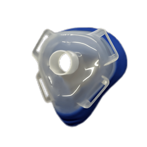
1TP11-Toleranz-Toleranzdiskussionen erhalten m, weil zwei unterschiedliche Mechanismen, die die Form-5-Temperatur-Expansion und die Schrumpfung nach der Aushärtung kühlen, sowohl das Dimensionsergebnis bewegen als auch die meisten Designreferenzen sie in einer einzigen “Schrumpfrate”zusammenklappen.” Die Entwirrung des Mechanismus ist der Unterschied zwischen einem Teil, das in der Spezifikation von der Presse abkommt, und eines, das während des ersten Produktionslaufs driftet.
Was tatsächlich dimensional geschieht, ist kontraintuitiv. 1TP15 T dehnt sich im Inneren der heißen Form aus Anstatt zu schrumpfen Volumetrische Hohlraumfüllung in einem funktionierenden 1TP15 T-Programm zielt auf 98 –991TP20 T, so dass die Materialausdehnung die Füllung abschließt, und es besteht Haltedruck, um zu verhindern, dass der expandierende Gummi durch das Tor zurückgedrängt wird, nicht um die Schrumpfung auszugleichen Messung dieses Ausdehnungsverhaltens wird gesteuert durch ISO 17744 (spezifisches Volumen als Funktion von Temperatur- und Druck-pvT-Diagrammen).
Schrumpfung geschieht, nachdem das Teil die Form verlassen hat, Wenn das Teil auf Raumtemperatur abkühlt, zieht es sich ungefähr 2,5 –5 31 TP20 T zusammen, und ein Nachhärtungszyklus (oft erforderlich für medizinische und Hochtemperaturqualitäten) fügt einen weiteren 0,50,71 TP20 T oben hinzu. A Momentive Silopren LIM 6061 Datenblatt Berichtet über eine lineare Schrumpfung von 0,027 in/in (2,71TP20 T) nach einer 10-sekündigen Vulkanisation bei 200 °C ohne Post-Cure-Landung im selben Band Schrumpfung in Strömungsrichtung verläuft höher als senkrecht, und dickere Abschnitte schrumpfen weniger als dünne, weshalb Teile mit gemischter Wandstärke eine pro Region abgestimmte Hohlraumskalierung anstelle eines einzigen gleichmäßigen Schrumpffaktors benötigen.
| Toleranzklasse | Erreichbare Reichweite (mm) | Wo es verwendet wird | Kostenauswirkungen |
|---|---|---|---|
| Präzision (Klasse A) | ±0,025 05 Uhr | Dichtungsflächen, optische, dynamische Dichtungen | Höchster Bedarf an dichtem Hohlraum, validierte Aushärtung |
| Standard (Klasse B) | ±0,05 –1 | Die meisten Produktionsteile, Gasgehäuse, Griffe | Ausgangswert |
| Kommerziell (Klasse C) | ±0,1 –2 | Unkritische Merkmale, dekorativ | Niedrigster Wert, aber schlechte Passform zum Versiegeln |
| Enger als ±0,025 | <±0,025 | Spezialität nur für die Sekundärbearbeitung oder das Schleifen | Extreme ein Redesign-Signal |
Wenn ein kritisches Dichtungsmaß innerhalb von ±0,05 mm von einer Trennlinie landet, fordern Sie einen Prototyplauf an, bevor der Produktionswerkzeugstahl geschnitten wird. Das Trennlinienverhalten unter Druck verändert das Dimensionsergebnis auf eine Weise, die eine reine Hohlraummessung nicht vorhersagt.
Für Programme zur Bewertung von 1TP15 T gegen thermoplastische Elastomere auf Toleranzbasis ist die LSR vs. TPE-Vergleich Spaziergänge durch die Kompromisse in großem Maßstab.
Zugwinkel: Wenn Sie ihn brauchen und wann Sie ihn überspringen können
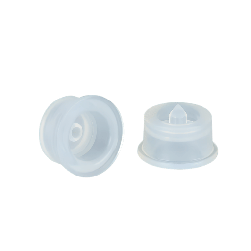
Draft ist die 1TP15 T Regel Designer am häufigsten über-apply Tragen Sie über den thermoplastischen Instinkt von “immer überall hinzufügen 1°” erzeugt unnötige kosmetische Werkzeugspuren auf flachen Oberflächen und verkompliziert die Dichtungsgeometrie, wo Zugluft würde die Dichtungsfunktion beeinträchtigen.
Was ist der minimale Zugwinkel für 1TP15 T?
Ein Grad ist der Entwurf für die 1TP15 T-Einspritzung Vertikale Flächen 0,5° Abschaltbedingungen tolerieren jeweils zwei gemeinsame Formhälften versiegeln gegen einander auf der Teiloberfläche 3° Leicht strukturierte Oberflächen beginnen im Allgemeinen bei 3°, und mittlere Texturen bei 5° oder mehr Flache Geometrien können manchmal mit Nullzug geformt werden, da die hohe Dehnung von 1TP15 T eine elastische Freisetzung über kleine Merkmale hinweg ermöglicht.
| Oberflächenzustand | Empfohlener Entwurf | Begründung |
|---|---|---|
| Vertikal (parallel zu zeichnen) | 0.5° | Minimum, um zu verhindern, dass hohe Wände hängen bleiben |
| Allgemeinste Merkmale | 1° | Standardeinstellung nach Industriestandard; saubere Freigabe |
| Die meisten Situationen (technisch) | 2° | Verbessert die Zykluszeit auf automatisierten Zellen |
| Absperrflächen | 3° | Schützt passende Werkzeugoberflächen vor Verschleiß |
| Leichte Textur (PM-T1 / VDI 18) | 3° | Die Texturtiefe erhöht die Entformungskraft |
| Mittlere Textur (PM-T2 / VDI 30) | 5°+ | Erforderlich, um bei der Freigabe Bremsspuren zu vermeiden |
Diese Werte konvergieren über mehrere LSR-Designreferenzen hinweg und haben eine Laufzeit von zwei Jahrzehnten. Es handelt sich eher um Arbeitsausfälle als um erste Prinzipien, die Ihre Geometrie stabil halten. Durometer und Oberflächenbeschaffenheit bestimmen die endgültige Wahl. Wenn ein Dichtungsmerkmal den Tiefgang wirklich nicht verträgt (eine O-Ring-Nutfläche, eine flache Dichtungsfelge), behandeln Sie dies als dokumentierte Ausnahme und bezahlen Sie dafür entweder in einer komplexeren Werkzeugwirkung oder in einem etwas längeren Zyklus.
💡 Pro Tip, überall nicht Standard Draft
Durch Hinzufügen von 1° zu einer flachen 5 mm Kosmetikfläche entsteht eine Verjüngung von 0,087 mm, die bei einem glänzenden Finish unter dem Rechenlicht sichtbar wird, wo die Oberfläche flach und nicht tragend ist, ist Nullzug mit elastischer Freigabe die bessere Antwort als ein reflexives 1°.
Unterschneidungen, Trennlinien und Gating-Strategie
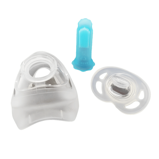
Diese drei Entscheidungen teilen sich eine Wurzel: Wo die Form spaltet Holen Sie sich die Aufteilung richtig und Hinterschneidungen, Trennblitz und Gate-Überreste werden alle beherrschbar; Verstehen Sie es falsch und jedes nachgeschaltete Problem wird zusammengesetzt.
Unterschneidet Sind einer der strukturellen Vorteile von 1TP15 T. Weil ausgehärtetes 1TP15 T eine Dehnung von mehreren hundert Prozent hat, werden einfache Hinterschneidungen in der Größenordnung von 301TP20 T von Teiltiefe typischerweise manuell oder mit leichter Luftunterstützung freigesetzt, keine Schlitten, Heber, oder cam benötigt Darüber hinaus werden mechanische Aktionen notwendig, und diese addieren ungefähr 25401TP20 T zu Werkzeugkosten je nach Anzahl und Komplexität Wenn ein Unterschnitt ein reiner Montagekomfort ist, neu gestalten Sie ihn um, wenn er funktionell erforderlich ist (eine Schnappverhaltung, eine unverschlissene Siegellippe), bewerten Sie die Systemkosten, Validierungsaufwand, Automatisierung, Automatisierung, Delta und Werkzeugwartung nicht nur das Upfront-Tool.
LSR-Umspritzung Über einem thermoplastischen Substrat wird das hinterschnittene Design zusätzlich eingeschränkt, da sich das Substrat während der Freisetzung nicht verformen kann. Planen Sie eine hinterschnittene Tiefe um die Toleranz des starren Substrats herum, nicht um die Elastizität des LSR.
Trennlinien Einfachheit belohnen Drei Regeln aus der Produktionserfahrung:
- Vermeiden Sie es, eine Trennlinie durch kritische Dichtungsoberflächen zu führen. Der Blitz der Trennlinie hinterlässt, selbst wenn er beschnitten wird, einen Zeugen, der die Dichtungsintegrität beeinträchtigt.
- Legen Sie die Linie so, dass das Teil während des Öffnens vorhersehbar auf einer Formhälfte bleibt. LSR verträgt selten Auswerferstifte (das Stiftpolster wird zu einer dauerhaften kosmetischen Narbe), daher ist die Teileretention ein Layoutproblem und kein Auswurfproblem.
- Die Linie auf nicht-kosmetischer Geometrie ausblenden, wo es möglich ist Eine Linie auf einer Flanschkante ist unsichtbar; eine Linie über einer Klasse-A-Fläche ist ein Ruf nach Leben.
Tore Für LSR laufen kleinere als thermoplastische Äquivalente Untertore mit einem Durchmesser von 0,51,0 mm sind üblich, wenn Thermoplast 1,53,0 mm verwenden würde, da die Viskosität von LSR unter Scherung stark abnimmt und ein kleineres Tor bessere kosmetische Ergebnisse liefert. Gummitechnikforen berichten konsequent über die Produktion-Boden-Praxis von Lüftungsschlitzen um 0,0002 Zoll Tiefe und Toren um 0,002 Zoll (Figuren, die seit mindestens 2002 gehalten werden und mit dem im nächsten Abschnitt besprochenen Blitzschwellenwert übereinstimmen.
Häufiger Fehler beim Tor auf einer Oberfläche der Klasse A
Designer platzieren gelegentlich Tore auf flachen dekorativen Oberflächen, weil dort die Wand am dicksten ist und die Strömung am einfachsten aussieht. Selbst nach der sekundären Verkleidung telegrafiert ein Torrestige durch jedes glänzende Finish unter direktem Licht. Bewegen Sie das Tor zu einer Aussparung, einer Kante oder einem nicht sichtbaren Flansch. Wenn die Geometrie ein Tor auf eine sichtbare Fläche drückt, entwerfen Sie eine 0,3-mm-Kosmetikaussparung, um die Überreste unter der Teileoberfläche einzufangen.
Blitz-, Heilungsverhalten und Auswurfplanung
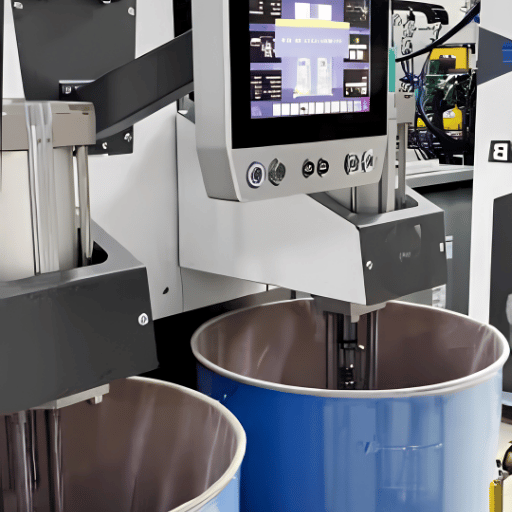
Blitz und Auswurf werden als Produktionsprobleme behandelt, aber die meisten dieser Probleme werden in Monaten früher in der Phase der Geometrie- und Werkzeugstrategie entwickelt. Sie dann zu lösen ist billig; Sie in der Produktion zu lösen ist teuer.
Wann tritt beim 1TP15 T-Formteil ein Blitz auf?
Flash tritt auf, wenn die Formspalte etwa 0,0002 Zoll (0,005 mm) oder mehr erreichen. Die niedrige Viskosität von LSR bei Einspritztemperaturen bedeutet, dass es in Lücken fließt, die ein Thermoplast nicht erreichen würde. Werkzeugdichtheit, Trennliniengeometrie und Entlüftungsstrategie sind die drei Steuerelemente; Alle drei benötigen ab der ersten Designüberprüfung Aufmerksamkeit.
Die Zeitmessung des Fensterfensters ist ähnlich eng. LSR-Härtungen in Formen mit einer Temperatur von 250 °C (121 204 °C), wobei die meisten Produktionsprogramme im 320-6450 °F-Band (160 232 °C) dokumentiert sind Die 1TP15 T-Werkzeugreferenz von Plastics Technology. Pressfässer und Düsen bleiben wassergekühlt, um eine vorzeitige Vernetzung durch Scherheizung zu verhindern; nur die Form liefert die Aushärteenergie. Aus diesem Grund sind 1TP15 T-Werkzeuge mechanisch anspruchsvoller als thermoplastische Werkzeuge: dicht, flach, gut belüftet und thermisch mit Wasser- und Ölkreisläufen gesteuert.
Auswurf Seltener wird mit herkömmlichen Auswerferstiften gearbeitet Pin-Pads telegrafieren durch ausgehärtetes 1TP15 T als kleine flache kreisförmige Abdrücke, die jeden sekundären Prozess überstehen Produktionswerkzeuge setzen stattdessen auf Teilehaltung (das Teil bleibt von der Konstruktion her auf einer Hälfte), manuelles Entfernen, Luftunterstützung oder Roboter-Picker Für Programme, die über ~250.000 Teile pro Jahr skalieren, planen Sie den Automatisierungs-Pickoff-Pfad während des ersten Entwurfs ein Teil, das sauber freigibt, ist einfacher zu validieren und mit Durchsatz auszuführen als eines, das den Druckbetreiber bekämpft.
s Technische Hinweise, Zykluszeitbänder
Realistische 1TP15 T-Zyklen laufen 30-690 Sekunden Klemm-zu-Klemm, abhängig von der Schussgröße, dem Härter und der Automatisierung. Die 250-Tonnen-Vakuumpresse von Engelhardt hat einen Durchschnitt von 4555 Sekunden auf einem Werkzeug mit 16 Kavitäten und ausgehärtetem Shore A 50-Material. Weiche Qualitäten (Shore 530) dauern länger, da sich die Aushärteenergie durch konformeres Material ausbreiten muss; Harte Qualitäten (Shore 70+) heilen schneller, erfordern aber eine aggressivere Demontagekontrolle.
DFM-Workflow: Vom Prototyp-Tool zum Produktionstool
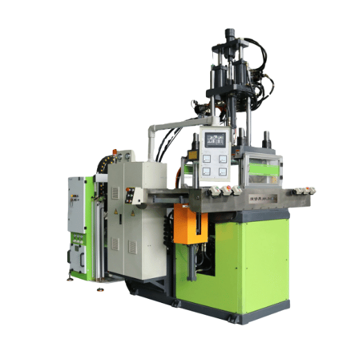
Den meisten 1TP15 T-Programmen, die Probleme in der Produktion trafen, fehlte ein Workflow und keine Daten Ein fünfstufiger Pfad unten ist der, der Probleme ständig fängt, solange sie noch billig zu beheben sind.
- Materialschloss. Lösen Sie Qualität, Härtemesser und Zusatzstoffe gegen Betriebstemperatur, Sterilisationsmethode und Patientenkontaktdauer. Sperren Sie, bevor eine Geometrie fertiggestellt ist.
- Geometriefrieren. Wenden Sie die Regeln für Wand, Rippe, Tiefgang, Trennlinie und Tor aus den oben genannten H2s an Führen Sie das Design durch eine interne Checkliste, bevor Sie ein Angebot anfordern.
- Prototypenwerkzeug (Mildwerkzeugstahl). Schneiden Sie eine Prototypform mit 1 oder 2 Hohlräumen Validieren Sie den Durchfluss, das Aushärtungsprofil, das Trennlinienverhalten und das Dimensionsergebnis unter realistischen Verarbeitungsbedingungen. Diese oder zwei Wochen Presszeit sind die günstigste verfügbare Versicherung.
- Pilotlauf. Produzieren Sie 100 – 500 Teile unter Quasi-Produktionsbedingungen Messen Sie die Toleranzverteilung, charakterisieren Sie den Blitz, dokumentieren Sie etwaige kosmetische Anomalien Ändern Sie das Prototyp-Tool nach Bedarf.
- Produktionswerkzeug (420 vorgehärteter Edelstahl). Schneiden Sie die Produktionshöhlenanordnung typischerweise 8 bis 64 Hohlräume je nach Volumen Die branchenzitierte Werkzeuglebensdauer für 420 SS im 1TP15 T-Dienst liegt in der Größenordnung von 1 Million Zyklen, wobei die tatsächliche Lebensdauer von der Komplexität der Teile, der Wartungsdisziplin und der Aggressivität des Werkzeugs abhängt.
Für die meisten Programme ist diese Sequenz nicht verhandelbar Ein “Skip Prototyp” - Zweig ist nur erlaubt, wenn drei Bedingungen alle gelten: Toleranzklasse ist C (kommerziell), Shore A sitzt im gut bewährten 30-Om60-Bereich, und die Teileleitung ist einfach Außerhalb dieser Hülle bedeutet das Überspringen von Werkzeug teuren Hohlraum schneiden gegen nicht überprüfte Annahmen & die Nacharbeit kostete Zwergkalenderzeit die gesicherte Abkürzung Führen Sie die Geometrie durch Engelhardt's LSR Kostenschätzer Für eine Machbarkeitsnummer vor der Entscheidung.
1TP2 T liefert neue 1TP15 T-Formen in 30 –50 Tagen ab Anpfiff, wobei das längere Ende für Werkzeuge mit hoher Kavitätszahl reserviert ist, die eine Dreiplatten- oder Hot-Runner-Konstruktion erfordern.
Die 0,010 / 1° / 0,5-×W-Regel
Drei Zahlen, die es wert sind, für jedes 1TP15 T-Design-Gespräch auswendig gelernt zu werden:
- 0,010 Zoll 0,010 Zoll Mindestwand, mit Durchfluss-Balance-Überprüfung unter 015.
- 1 Grad, Arbeitsentwurf hoch, skaliert auf Aussperrungen und Textur, manchmal skaliert auf null flache Merkmale.
- 0,5 ×, abhängig vom Verhältnis der Rippendicke, im Bereich von bis zu 1,0 × und Belastung.
Landen Sie alle drei vor dem ersten Angebot, fordern Sie ein Prototyp-Werkzeug an, und das Layout der Produktionshöhle hat ein vertretbares Fundament Überspringen Sie eines davon und das Produktionstool wird zum Prototyp.
Ein 3-Fragen-Gatter sitzt vor dem Schneiden eines Produktionswerkzeugstahls: Sind Toleranzen am Prototyp nachgewiesen, wurde das Blitzlicht zur Zeit des Produktionszyklus charakterisiert und ist das Aushärtungsprofil über die geplante Kavitation stabil? Ein “Nein” zu einem der drei sendet das Programm zurück zu Schritt 4, nicht weiter zu Schritt 5.
Häufig gestellte Fragen
F: Was ist der Unterschied zwischen 1TP15 T und HCR (hochkonsistenter Gummi)?
Antwort anzeigen
1TP15 T ist ein zweiteiliges flüssiges platingehärtetes Silikon, das bei Raumtemperatur in eine beheizte Form eingespritzt wird; HCR ist ein höherviskoses festes Silikon, das auf einer Mühle vermischt und durch Kompression, Transfer oder Extrusion verarbeitet wird. 1TP15 T ermöglicht höhere Kavitation, schnellere Zykluszeiten (3090 Sekunden vs. 210 Minuten) und engere Toleranzen (±0,0250,05 mm vs. ±0,080,15 mm). HCR wird weiterhin für sehr große Teile, Produktion mit geringem Volumen und bestimmte peroxidgehärtete Qualitäten bevorzugt.
Der Heilungspfad von HCR nutzt die Peroxidchemie ohne zusätzliche Härtung. Die Empfindlichkeit der Topfzeit bleibt daher bei einigen Legacy-Programmen bei HCR, selbst wenn 1TP15 T eine bessere Einheitsökonomie bieten würde.
F: Wie lange halten 1TP15 T-Formen in der Produktion?
Antwort anzeigen
Die branchenspezifische Lebensdauer des Werkzeugs für 420 vorgehärteten Edelstahl im 1TP15 T-Service beträgt etwa 1 Million Zyklen. Die tatsächliche Lebensdauer hängt von der Teilkomplexität (scharfe Ecken und dünne Merkmale verschleißen schneller), der Wartungsdisziplin (Lüftungsreinigung, Teiloberflächenprüfung) und der Betriebsgeschwindigkeit ab. Prototypformen aus Leichtwerkzeugstahl werden normalerweise nach 10.000 bis 50.000 Zyklen eingestellt.
F: Kann 1TP15 T über ein thermoplastisches Substrat geformt werden?
Antwort anzeigen
Yes-shot this-two-shot oder multi-shot Meitu Engelhardt Umspritzen Ein thermoplastisches Substrat muss die Formtemperatur (oft 320 4 °F) ohne PBT, PA66 und PEEK tolerieren sind gängige Substratwahl Substratoberflächen werden oft plasmabehandelt oder chemisch grundiert, um eine dauerhafte 1TP15 T-zu-Substrat-Haftung zu erreichen Die Zykluszeit läuft länger als Single-Shot 1TP15, da das Substrat zuerst geformt werden muss.
F: Welche Sterilisationsmethoden sind mit medizinischem LSR kompatibel?
Antwort anzeigen
Medizinisch hochwertiges 1TP15 T ist biokompatibel und toleriert Dampfautoklaven (121 135 °C), Ethylenoxid (EtO) und Gammastrahlung Wiederholte Autoklavenzyklen verursachen eine mäßige Härtedrift über Hunderte von Zyklen; Gamma bei hohen Dosen kann die Reißfestigkeit auf bestimmten Graden verändern Datenblätter des Silikonlieferanten bleiben die maßgebliche Referenz für bestimmte Grenzwerte.
F: Wie viel kostet eine 1TP15 T-Spritzgussform?
Antwort anzeigen
1TP2 T-Produktionswerkzeuge fallen im Bereich $15.000,0$80,000 je nach Kavitation, Komplexität, und Material-Einzelhöhlen-Prototyp-Werkzeuge sitzen am unteren Ende, Mehrhöhlen-Produktionswerkzeuge mit Kaltläufer-Verteilern am oberen Ende Programme mit hoher Kavitätszahl (3264 Hohlräume) für medizinische oder automobile Volumina können diesen Bereich überschreiten Nutzen Sie frühzeitig einen Kostenschätzer, um Designambition mit Budgetrealität in Einklang zu bringen.
F: Warum zeigt mein 1TP15 T-Teil auch nach der Bereinigung einen Parting-Line-Blitz?
Antwort anzeigen
Anhaltendes Entspannungsspuren führen zu einer von vier Ursachen: Verschleiß der Trennfläche, der den Verschlussspalt über der Entspannungsschwelle von 0,0002 Zoll öffnet, zu tief eingeschnittene Entlüftungstiefen während der Erstmontage, höherer Haltedruck als für die Füllung erforderlich oder eine Trennlinie, die durchläuft einen Bereich mit erheblicher Strömung. Überprüfen Sie zunächst die Ebenheit der Trennfläche und reduzieren Sie dann schrittweise den Haltedruck, bevor Sie eine Werkzeugreparatur in Betracht ziehen.
F: Wann sollte ich den Prototyp 1TP15 T vs. direkt zum Produktionswerkzeug springen?
Antwort anzeigen
Überspringen Sie den Prototyp nur, wenn drei Bedingungen alle halten: Toleranzklasse ist C (kommerziell), Shore A sitzt im bewährten 30-a-Train-Bereich, und die Trennlinie ist einfach ohne kritische Dichtungswechselwirkung Außerhalb dieses Umschlags zahlt das Prototyp-Werkzeug durch vermiedene Nacharbeit an Produktionsstahl zurück Prototyping in einem 1 - oder 2-Hohlraum-Mildstahlwerkzeug läuft ungefähr 10201TP20 T der Produktion Werkzeugkosten; Nachschneiden von Hohlräumen in einem Fertigungsgrad 420 SS-Werkzeug läuft 60801 TP20T.
Benötigen Sie eine DFM-Überprüfung Ihres LSR-Designs?
Das Ingenieurteam von Engelhardt überprüft 1TP15 T-Geometrien anhand der oben genannten Regeln und gibt eine Bewertung der Teilemachbarkeit mit Kavitationsempfehlungen und Toleranzprognosen zurück.
Über diese Referenz
Dieses DFM stützt sich auf Engelhardts 1 TP20 T-Formen 150 T-Referenzjahre 150 T-Formen 50-Referenz 5, einschließlich einer 150-Ton-1TP15-Presse, einer 2-Tonnen-Vakuumpresse und einer 1.200-Tonnen-Großformat-Vakuumzelle, plus der 1TP3 T-Qualitätsdisziplin, die von Kfz-Siegelprogrammen übernommen wurde Die als Erstdaten genannten Wanddicken-, Zykluszeit- und Toleranzzahlen wurden anhand von Werkzeugen validiert, die für Kohler, American Standard, Amphenol, Oatey und SFA zwischen 2015 und 2025. Wenn eine Anzahl auf die primäre Unsicherheit der Industrie-Guide-Quelle zurückzuführen ist, statt auf eine primäre Quelle zurückzuführen.
Referenzen und Quellen
- Verwendung der internationalen Norm ISO 10993-1, Biologische Bewertung medizinischer Geräte „Eine Lebensmittel- und Arzneimittelverwaltung
- Fortschritte bei der Charakterisierung von Silikonimplantaten Nationale Gesundheitsinstitute, Pub Central
- Bewertung der Biokompatibilität von Silikongel-Implantaten Nationale Gesundheitsinstitute, Pub Central
- Richtlinien für feste und flüssige Kautschukmaterialien und -verarbeitung (ELASTOSIL LR-Verarbeitungshandbuch) Chemie AG
- Momentive Silopren LIM 6061 Datenblatt Mattentive Performance Materials, über MatWeb
- ISO 1774:2004 Kunststoffe, Bestimmung des spezifischen Volumens als Funktion von Temperatur und Druck Organisation für Standardisierung
- Einstieg in LSR Teil IV: Wie sich LSR-Tooling unterscheidet Technologie
Verwandte Artikel
- Leitfaden zum Formen von flüssigem Silikonkautschuk 15 T-Prozessübersicht
- Silikon gegen Gummi Familienvergleich und Auswahlführer
- Spritzgusstoleranzen Referenz zum Prozess
- Shore A Durometer Guide Auswahl von Elastomerprogrammen
![Silikon-Überspritzung: Multi-Material 1TP15 T Design Guide [2026]](https://meitu-engelhardt.com/wp-content/uploads/2026/04/0-8-768x512.png)