Entrez en contact avec Engelhardt


Ce que les ingénieurs de conception doivent savoir avant de verrouiller les données de tolérance de première partie et les règles de décision d'une cellule 1TP15 T de classe 7 produisant plus de 1 000 tonnes par an.
Ces directives de conception 1TP15 T répondent aux questions qui comptent avant qu'une seule cavité de moule ne soit découpée : quelle épaisseur une paroi peut être sans porosité, quelle quantité de retrait attendre après la sortie de la presse de la pièce, quand le tirage n'est pas négociable et quand il peut être sauté, et où le flash apparaîtra si la ligne de séparation atterrit au mauvais endroit Le caoutchouc de silicone liquide ne se comporte en rien comme les thermoplastiques que la plupart des concepteurs de produits apprennent en premier, et le transport des instincts thermoplastiques dans un programme 1TP15 T est l'erreur la plus coûteuse que nous voyons au stade du prototype.
Coup d'œil : spécifications de conception LSR
Avant de travailler à travers les sections individuelles, cette carte Quick Specs regroupe les huit numéros les plus fréquemment demandés par les concepteurs de mécanique et de produit qui démarrent un programme 1TP15 T. Utilisez-les pour une référence rapide ; le raisonnement complet vit dans les sections H2 ci-dessous.
Spécifications rapides Conception de moule LSR
| Épaisseur minimale de la paroi | 0,010 po (0,254 mm) : réalisable avec un essai d'équilibre des flux |
| Règle d'épaisseur de la côte | 0,5 épaisseur de paroi adjacente.0.0 |
| Angle de tirage standard | 1° commune ; 0,5° faces verticales ; 3°+ pour les surfaces texturées |
| Tolérance réalisable | ±0,0250,05 mm (plancher Engelhardt)/±0,08 mm typique |
| Rétrécissement post-durcissement | 2,53TP20T pendant le refroidissement + 0,50,7% après le durcissement |
| Seuil de flash | Lacunes de moule ≥ 0,0002 po (0,005 mm) fuite |
| Bande de temps de cycle | 300 sec (cellule 1TP 250 T, ligne de base 16 cavités 455 sec) |
| Délai d'exécution de l'outillage | 30 50 jours nouveau moule ; 40 SS outil de production ≈ 1M cycles |
Sélection du matériau : duromètre, qualités et additifs
Les décisions matérielles passent avant les décisions géométriques dans un programme 1TP15 T fonctionnel Le duromètre entraîne la faisabilité des murs, la dimensionnement des portes et le comportement de démoulage : choisissez d'abord la mauvaise valeur Shore et redessinez la pièce plus tard.
Le 1TP15 T est un thermodurci durci par addition (catalysé au platine) en deux parties, injecté à froid dans un moule chauffé où il se réticule de façon irréversible Le duromètre commercial standard couvre 30, 40, 50, 60 et 70 Shore A. Engelhardt services personnalisés de moulage par injection LSR détenez une gamme plus large de 550 Shore A sur plus de 1 000 tonnes de production annuelle, les qualités de duromètre inférieur étant réservées aux joints souples et l'extrémité supérieure aux joints industriels.
Pour les applications médicales, la sélection Shore n'est que le début Branche des grades de matériaux en quatre catégories de travail, chacune liée à un parcours de qualification différent :
- Norme LSR : joints industriels, joints, produits de cuisine et de consommation Aucune documentation de biocompatibilité requise.
- LSR de qualité médicale rencontre Évaluation de la biocompatibilité FDA selon ISO 10993 et souvent USP Classe VI. Généralement également produit selon la norme ISO 13485.
- LSR de qualité optique pour lentilles, conduits de lumière et boîtiers translucides ; exige une propreté contrôlée pendant le traitement.
- Fluorosilicone : résistance au carburant et à l'huile ; allongement inférieur, coût plus élevé.
Les dispositifs implantables ajoutent une dimension réglementaire Les directives 1TP10 T distinguent l'implantation à court terme (≤29 jours) de l'implantation à long terme (>29 jours ou permanente), et le profil de test s'intensifie en conséquence. Un examen de 2024 évalué par des pairs progrès dans la caractérisation des implants en silicone documente comment les interactions hôte-tissu varient avec la préparation de la surface, le duromètre et les remplissages. Il rappelle que le“ de qualité technique médicale est un point de départ plutôt qu'une garantie.
💡 Pré-vol matériel à trois questions
Avant d'ouvrir un modèle CAO, répondez à ces trois questions :
- Quelle température de service continue la pièce voit-elle ? (Détermine si la norme 1TP15 T ou la fluorosilicone est nécessaire.)
- Quelle méthode de stérilisation applique l'autoclave, l'EtO, le gamma ou aucun ? (Élimine les qualités non compatibles.)
- Y a-t-il un contact avec le patient, et pour combien de temps ? (Détablit la portée des tests ISO 10993 /USP Classe VI.)
Verrouiller ces trois questions tôt empêche la plupart des refontes axées sur la réglementation Utiliser le Calculateur de sélection de matériaux LSR pour mapper les réponses à une note de départ.
Épaisseur des murs, côtes et transitions de section
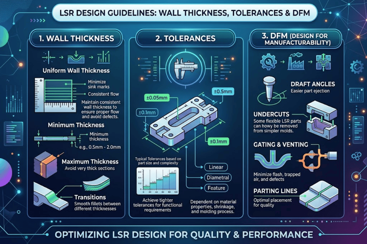
L'épaisseur de paroi entraîne presque tous les coûts en aval : nombre de cavités, temps de cycle, équilibre du débit et taux de rejet de la porosité. Le plancher industriel publié se situe à 0,010 po (0,254 mm), mais traiter ce nombre comme un minimum occasionnel est une recette pour des douleurs d’essai de moulage.
Quelle peut être la minceur des parois 1TP15 T ?
L'injection de 1TP15 T peut remplir des parois aussi fines que 0,010 po (0,254 mm), et les programmes spécialisés atteignent en dessous. Manuel de traitement ELASTOSIL LR de Wacker décrit le système de durcissement catalysé au platine qui rend pratique l'écoulement en section mince, avec une chute de viscosité sous cisaillement dans le canal et la porte La profondeur pratique du sol dépend de trois choses : la taille de la région mince, l'emplacement des sections adjacentes plus épaisses et la façon dont la cavité est ventilée de manière agressive.
“La presse 1TP15 T de 150 tonnes remplit régulièrement des murs de 0,020 pouce sur des outils à 64 cavités En dessous de 0,015 pouce, nous effectuons un essai d'équilibre des flux dans le moule prototype avant de nous engager dans la disposition de production. Cet essai d'environ une semaine de temps de presse coûte trivialement par rapport à la coupe d'un outil à 64 cavités qui ne se remplira pas uniformément.”.”
Les praticiens de l'industrie rapportent que les pièces 1TP15 T à paroi mince sont normalement moulées dans des outils à cavité 3050 plutôt que dans des configurations expérimentales plus petites, car l'économie de production exige une cavitation élevée une fois la géométrie prouvée.
Les règles de côtes viennent ensuite, et elles surprennent les concepteurs qui traversent le thermoplastique Dans l'injection thermoplastique, les nervures courent généralement 5060% de l'évier de contrôle mural attenant En 15 T, la plage de travail est de 0.5.1.0 la paroi attenante 1.0 plus large, parce que le profil de retrait entraîné par durcissement de Meitu Engelhardt diffère et parce que les nervures surdimensionnées rigidifient la pièce de manière à modifier la force de démoulage. Les filets intérieurs doivent se rapprocher de l'épaisseur de la paroi ; plus tranchants ou plus ronds que ceux qui risquent la porosité lors de la transition.
📐 Note d'ingénierie : géométrie des côtes
Utilisation rib_t = 0,7 × attenant_wall_t comme point de départ Pour Shore A 60 (grades de joint industriel), 1,0.1 est acceptable lorsque la nervure est chargée en compression. Valider dans l'outil prototype DFM rework après la coupe de l'outil de production court de quatre à dix fois le coût d'un essai de bilan de débit.
Les transitions de section comptent autant que l'épaisseur de paroi elle-même, Passer directement d'une paroi de 1,5 mm à un bossage de 4 mm crée un déséquilibre de durcissement : la région mince a fini de vulcaniser alors que la zone épaisse est encore en train de durcir, et la pièce en ressort avec une chaîne localisée ou une porosité de surface Étape la transition sur au moins 3. le delta de paroi, ou utilise un congé effilé plutôt qu'un changement étagé référence des tolérances de moulage du caoutchouc détaille comment la géométrie de transition alimente directement la classe dimensionnelle réalisable.
Tolérances, rétrécissement et précision dimensionnelle
Les discussions sur la tolérance 1TP15 T sont confuses car deux mécanismes distincts : l'expansion de la température de moule et le retrait du refroidissement post-durcissement, déplacent tous deux le résultat dimensionnel, et la plupart des références de conception les regroupent en un seul taux de retrait. Le déploiement du mécanisme est la différence entre un pièce qui sort de la presse en spécifications et une pièce qui dérive lors du premier cycle de production.
Ce qui se passe réellement dimensionnellement est contre-intuitif. 1TP15 T se dilate à l'intérieur du moule chaud plutôt que de rétrécir Le remplissage de la cavité volumétrique dans un programme 1TP15 T fonctionnel cible 9891TP20 T de sorte que l'expansion du matériau complète le remplissage, et la pression de maintien existe pour empêcher le caoutchouc en expansion d'être repoussé à travers la porte, et non pour compenser le retrait La mesure de ce comportement d'expansion est régie par ISO 17744 (volume spécifique en fonction de la température et de la pression : diagrammes pvT).
Le retrait se produit après que la pièce a quitté le moule, Comme la pièce refroidit à la température ambiante, il se contracte environ 2.5.3TP20 T, et un cycle de post-durcissement (souvent requis pour les qualités médicales et à haute température) ajoute encore 0.50.7% sur le dessus. A Momentive Silopren LIM 6061 datasheet signale un retrait linéaire de 0,027 po/po (2,71TP20 T) après une vulcanisation de 10 secondes à 200 °C sans post-durcissement (post-cure) °C à l'intérieur de la même bande Le retrait dans le sens de l'écoulement s'étend plus haut que perpendiculairement, et les sections plus épaisses rétrécissent moins que les sections minces, c'est pourquoi les pièces avec une épaisseur de paroi mixte ont besoin d'une mise à l'échelle de la cavité réglée par région au lieu d'un seul facteur de retrait uniforme.
| Classe de tolérance | Portée réalisable (mm) | Où il est utilisé | Impact sur les coûts |
|---|---|---|---|
| Précision (Classe A) | ±0,0250,05 | Surfaces d'étanchéité, joints optiques, dynamiques | La cavité la plus élevée nécessite une cavité serrée et un profil de durcissement validé |
| Standard (Classe B) | ±0,050,1 | La plupart des pièces de production, les joints, les poignées, les boîtiers | Base de référence |
| Commercial (Classe C) | ±0.10.2 | Caractéristiques non critiques, décoratives | Le plus bas mais mauvais ajustement pour le scellement |
| Plus serré que ±0,025 | <±0,025 | Spécialité uniquement usinage secondaire ou meulage | Extrêmement un signal de refonte |
Si une dimension d'étanchéité critique atterrit à moins de ±0,05 mm d'une ligne de séparation, demandez un prototype avant que l'acier de l'outil de production ne soit coupé. Le comportement de la ligne de séparation sous pression modifie le résultat dimensionnel d'une manière que la mesure uniquement dans la cavité ne prédira pas.
Pour les programmes évaluant le 1TP15 T contre les élastomères thermoplastiques sur une base de tolérance, le Comparaison 1TP15 T vs TPE passe par les compromis à grande échelle.
Angle de brouillon : quand vous en avez besoin et quand vous pouvez le sauter
Draft est le plus souvent sur-appliquer les concepteurs de règles LSR. Reporter l'instinct thermoplastique de “ajouter toujours 1° partout” crée des marques d'outils cosmétiques inutiles sur les surfaces peu profondes et complique la géométrie du joint où le draft compromettrait la fonction d'étanchéité.
Quel est l'angle de dépouille minimum pour LSR ?
Un degré est le tirant d'eau courant pour l'injection de 1TP15 T. Les faces verticales tolèrent 0,5° Conditions d'arrêt (Shut-off) 2 moitiés de moule s'étanchéité l'une contre l'autre sur la surface de la pièce (besoin général de 3°) Les surfaces texturées légères commencent à 3°, et les textures moyennes à 5° ou plus Les géométries peu profondes peuvent parfois être moulées avec un tirant d'eau nul car le fort allongement de 1TP15 T rend possible la libération élastique sur de petites caractéristiques.
| Surface État | Projet recommandé | Justification |
|---|---|---|
| Vertical (parallèle au dessin) | 0.5° | Minimum pour éviter de coller sur les hauts murs |
| Caractéristiques les plus générales | 1° | Par défaut standard de l'industrie ; libération nette |
| La plupart des situations (conçues) | 2° | Améliore le temps de cycle sur les cellules automatisées |
| Surfaces d'arrêt | 3° | Protège les surfaces des outils d'accouplement de l'usure |
| Texture légère (PM-T1/VDI 18) | 3° | La profondeur de texture fait monter la force de démoulage |
| Texture moyenne (PM-T2/VDI 30) | 5°+ | Obligatoire pour éviter les marques de traînée lors de la libération |
Ces valeurs convergent à travers plusieurs références de conception LSR et sont restées stables pendant deux décennies. Ils fonctionnent par défaut plutôt que par des résultats de principes premiers : votre géométrie, votre duromètre et votre finition de surface déterminent le choix final. Lorsqu'une fonction d'étanchéité ne peut véritablement pas tolérer le tirage (une face de rainure de joint torique, un rebord d'étanchéité plat), traitez cela comme une exception documentée et payez-le soit dans une action d'outil plus complexe, soit dans un cycle légèrement plus long.
💡 Pro Tip : Ne faites pas de brouillon par défaut partout
L'ajout de 1° à une face cosmétique plane de 5 mm crée une conicité de 0,087 mm qui devient visible sous la lumière ratissante sur une finition brillante Là où la surface est peu profonde et non porteuse, un tirage nul avec libération élastique est la meilleure réponse qu'un 1° réflexif.
Sous-cotations, lignes de séparation et stratégie de déclenchement
Ces trois décisions partagent une racine : où le moule se divise. Bien diviser et les contre-dépouilles, le flash de séparation et le vestige de porte deviennent tous gérables ; se tromper et chaque problème en aval s'aggrave.
Sous-couche Sont l'un des avantages structurels de 1TP15 T. Parce que le 1TP15 T durci a un allongement atteignant plusieurs centaines de pour cent, de simples contre-dépouilles de l'ordre de 30% de profondeur de pièce généralement libèrent manuellement ou avec une légère assistance aérienne ; aucune glissière, lève-personne, ou came n'est nécessaire Au-delà, des actions mécaniques deviennent nécessaires, celles ajoutent environ 25401TP20 au coût de l'outil en fonction du nombre de complexité et Si une sous-dépouille est purement une commodité d'assemblage, repensez-la. Si cela est fonctionnellement requis (une rétention d'encliquetage, une lèvre de joint captif), évaluez le coût du système (travail, effort de validation, automatisation, automatisation, automatisation, et outil de maintenance de l'outil) et outil de l'outil de l'outil de delta non seulement).
Surmoulage LSR sur un substrat thermoplastique contraint encore plus la conception en contre-dépouille car le substrat ne peut pas se déformer pendant le relâchement Planifiez la profondeur de contre-dépouille autour de la tolérance du substrat rigide, et non de l'élasticité du LSR.
Lignes de séparation récompenser la simplicité Trois règles issues de l'expérience de production :
- Évitez de faire passer une ligne de séparation à travers les surfaces critiques du joint. Le flash de ligne de séparation, même lorsqu'il est coupé, laisse un témoin qui compromet l'intégrité du joint.
- Placez la ligne de manière à ce que la pièce reste, comme on pouvait s'y attendre, sur une moitié de moule pendant l'ouverture. 1TP15 T tolère rarement les broches d'éjection (le tampon de broche devient une cicatrice cosmétique permanente), donc la rétention de la pièce est un problème d'agencement et non un problème d'éjection.
- Cacher la ligne sur la géométrie non cosmétique lorsque cela est possible Une ligne sur un bord de bride est invisible ; une ligne sur un visage de classe A est un appel pour la vie.
Portes pour LSR courir plus petit que les équivalents thermoplastiques Des sous-gates de 0,51 mm de diamètre sont courants où le thermoplastique utiliserait 1.5.0 mm, car la viscosité de 1TP15 T chute fortement sous cisaillement et une porte plus petite donne de meilleurs résultats cosmétiques Les forums de génie du caoutchouc rapportent systématiquement la pratique des évents au sol de production autour de 0,0002 pouce de profondeur et des portes autour de 0,002 pouce chiffres qui ont tenu depuis au moins 2002 et s'alignent sur le seuil de flash discuté dans la section suivante.
⚠ Common Mistake sur une surface de classe A
Les concepteurs placent occasionnellement des portails sur des surfaces décoratives plates parce que c'est là que le mur est le plus épais et que le flux semble le plus facile Même après la garniture secondaire, un vestige de portillon télégraphie à travers toute finition brillante sous lumière directe Déplacez le portillon vers un renfoncement, un bord ou une bride non visible Si la géométrie force un portillon sur une face visible, concevez un renfoncement cosmétique de 0,3 mm pour capturer le vestige sous la surface de la pièce.
Planification du flash, du comportement de guérison et de l'éjection
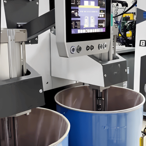
Le flash et l'éjection sont traités comme des problèmes de production, mais la plupart de ces problèmes sont conçus des mois plus tôt au stade de la géométrie et de la stratégie d'outillage. Les résoudre alors est bon marché ; les résoudre en production coûte cher.
Quand le flash se produit-il dans le moulage LSR ?
Le flash apparaît lorsque les espaces de moisissure atteignent environ 0,0002 pouce (0,005 mm) ou plus. La faible viscosité du 1TP15 T aux températures d'injection signifie qu'il s'écoule dans les espaces qu'un thermoplastique ne ferait pas. L'étanchéité à l'outillage, la géométrie de la ligne de séparation et la stratégie de ventilation sont les trois commandes ; tous trois nécessitent l’attention dès le premier examen de conception.
Le timing de la fenêtre de durcissement est tout aussi étroit. 1TP15 T durcit dans des moules fonctionnant à 250 400 °F (121204 °C), la plupart des programmes de production se situant dans la bande 320 450 °F (160 22 °C) documentée dans Référence d'outillage LSR de Plastics Technology. Les canons de presse et les buses restent refroidis à l'eau pour éviter une réticulation prématurée due au chauffage par cisaillement ; seul le moule délivre l'énergie de durcissement C'est pourquoi l'outillage 1TP15 T est mécaniquement plus exigeant que l'outillage thermoplastique : serré, plat, bien ventilé et thermiquement contrôlé avec des circuits d'eau et d'huile.
Éjection utilise rarement les broches d'éjection traditionnelles Les pin pads télégraphient via 1TP15 T durci comme de petites impressions circulaires plates qui survivent à tous les processus secondaires Les outils de production reposent plutôt sur la rétention des pièces (la pièce reste sur une moitié de par sa conception), le retrait manuel, l'assistance aérienne ou les cueilleurs robotisés Pour les programmes s'échelonnant au-dessus de ~250 000 pièces par an, planifiez le pickoff d'automatisation pendant la conception initiale une pièce qui libère proprement est plus facile à valider et à exécuter à un débit que celle qui combat l'opérateur de presse.
📐 Note d'ingénierie : bandes temporelles de cycle
Les cycles réalistes de 1TP15 T s'exécutent 3090 secondes pince à pince en fonction de la taille de tir, du duromètre et de l'automatisation La presse à vide de 250 tonnes de 1TP2 T dure en moyenne 455 secondes sur un outil à 16 cavités avec un matériau Shore A 50 de qualité durcie Les qualités douces (Shore 530) prennent plus de temps car l'énergie de durcissement doit se propager à travers un matériau plus conforme ; les qualités dures (Shore 70+) guérissent plus rapidement mais exigent un contrôle de démoulage plus agressif.
Flux de travail DFM : de l'outil prototype à l'outil de production
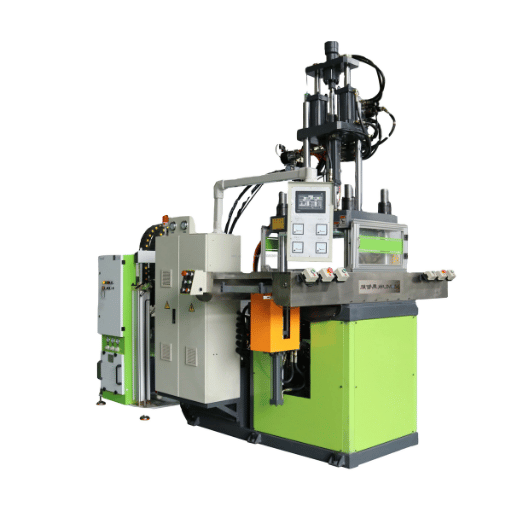
La plupart des programmes 1TP15 T qui ont rencontré des problèmes en production manquaient d'un flux de travail plutôt que de données. Un chemin en cinq étapes ci-dessous est celui qui résout systématiquement les problèmes alors qu’ils sont encore peu coûteux à résoudre.
- Serrure matérielle. Résolvez la qualité, le duromètre et les additifs par rapport à la température de service, à la méthode de stérilisation et à la durée de contact avec le patient. Verrouillez avant que toute géométrie ne soit finalisée.
- Gel géométrique. Appliquez les règles de mur, de côte, de tirant d'eau, de ligne de séparation et de porte des H2 ci-dessus Exécutez la conception via une liste de contrôle interne avant de demander un devis.
- Outil prototype (acier à outils doux). Couper un moule prototype à 1 ou 2 cavités Valider le débit, le profil de durcissement, le comportement de la ligne de séparation et le résultat dimensionnel dans des conditions de traitement réalistes Cette semaine ou deux de temps de presse est l'assurance la moins chère disponible.
- Course pilote. Produire 1000 pièces en quasi-production. Mesurer la distribution des tolérances, caractériser le flash, documenter les éventuelles anomalies cosmétiques Modifier l'outil prototype au besoin.
- Outil de production (acier inoxydable pré-durci 420). Coupez la disposition de la cavité de production 8 à 64 cavités généralement en fonction du volume. La durée de vie de l'outil indiquée par l'industrie pour 420 SS en service 1TP15 T est de l'ordre de 1 million de cycles, la durée de vie réelle dépendant de la complexité de la pièce, de la discipline de maintenance et de l'agressivité de l'outil.
Pour la plupart des programmes, cette séquence est non négociable Une branche de“ prototype de ”skip n'est autorisée que lorsque trois conditions sont toutes remplies : la classe de tolérance est C (commerciale), Shore A se situe dans la plage bien prouvée de 3060 et la ligne de pièce est simple. En dehors de cette enveloppe, sauter un outil prototype signifie couper l'acier coûteux contre des hypothèses non vérifiées et le coût de retouche nain le calendrier quel que soit le raccourci enregistré. Exécutez la géométrie sur Engelhardt Estimateur de coût LSR pour un numéro de faisabilité avant de décider.
Engelhardt propose de nouveaux moules 1TP15 en 300 à 50 jours du coup d'envoi, l'extrémité la plus longue étant réservée aux outils à grand nombre de cavités nécessitant une construction à trois plaques ou à courant chaud.
La règle 0,010 /1° /0,5×W
Trois nombres qui valent la peine d'être mémorisés pour toute conversation de conception LSR :
- Mur minimum pratique de 0,010 pouce, avec vérification de l'équilibre du débit en dessous de 0,015.
- tirage de travail par défaut de 1 degré, mis à l'échelle pour les arrêts et la texture, parfois mis à l'échelle à zéro sur les fonctionnalités peu profondes.
- 0,5 × mur × rapport d'épaisseur de côte de départ, allant jusqu'à 1,0.1.1.1. en fonction du duromètre et de la charge.
Atterrir tous les trois avant le premier devis, demander un outil prototype, et la disposition de la cavité de production a une fondation défendable Sauter l'un d'entre eux et l'outil de production devient le prototype.
Une porte à 3 questions se trouve avant de couper tout acier d'outil de production : les tolérances sont-elles prouvées sur le prototype, le flash a-t-il été caractérisé au moment du cycle de production et le profil de durcissement est-il stable tout au long de la cavitation prévue. Un approatino“ vers l'un des trois renvoie le programme à l'étape 4, et non pas à l'étape 5.
Foire aux questions
Q : Quelle est la différence entre le 1TP15 T et le HCR (caoutchouc haute cohérence) ?
Voir la réponse
LSR est un silicone durci au platine en deux parties injecté à température ambiante dans un moule ; HCR est un silicone solide à viscosité plus élevée composé sur un broyeur et traité par compression, transfert ou extrusion. LSR permet une cavitation plus élevée, des temps de cycle plus rapides (3090 secondes contre 210 minutes), des tolérances plus élevées (0,0250,05 mm contre 0,080,15 mm).). HCR reste préféré pour les pièces de grande taille, la faible production de peroxyde et certaines qualités de peroxyde.
La voie de guérison de HCR utilise la chimie du peroxyde sans la sensibilité de la vie en pot du durcissement par addition, c'est pourquoi certains programmes existants restent avec HCR même lorsque 1TP15 T offrirait une meilleure économie unitaire.
Q : Combien de temps durent les moules 1TP15 T en production ?
Voir la réponse
La durée de vie des outils cités par l'industrie pour l'acier inoxydable pré-durci 420 en service 1TP15 T est d'environ 1 million de cycles La durée de vie réelle dépend de la complexité des pièces (les coins pointus et les caractéristiques minces s'usent plus rapidement), de la discipline de maintenance (nettoyage des évents, inspection de la surface de séparation) et de la vitesse de fonctionnement. Les prototypes d'outils doux en acier se retirent généralement après 10 000 5000 cycles.
Q : Le 1TP15 T peut-il être moulé sur un substrat thermoplastique ?
Voir la réponse
Oui 32 température de moule 400 °F sans distorsion ; le PBT, le PA66 et le PEEK sont des choix de substrat courants Les surfaces de substrat sont souvent traitées au plasma ou chimiquement amorcées pour obtenir une adhérence durable du 1TP15 T au substrat. Le temps de cycle est plus long que le 1TP15 T à un seul coup car le substrat doit être moulé en premier.
Q : Quelles méthodes de stérilisation sont compatibles avec le LSR de qualité médicale ?
Voir la réponse
Le 1TP15 T de qualité médicale est biocompatible et tolère l'autoclave à vapeur (121135 °C), l'oxyde d'éthylène (EtO) et le rayonnement gamma. Les cycles répétés d'autoclave provoquent une dérive modeste de la dureté sur des centaines de cycles ; le gamma à fortes doses peut modifier la résistance à la déchirure sur certaines qualités Les fiches techniques de qualité du fournisseur de silicone restent la référence faisant autorité pour les limites spécifiques.
Q : Combien coûte un moule d'injection 1TP15 T ?
Voir la réponse
L'outillage de production Engelhardt se situe dans la gamme $15,0000$80,000 en fonction de la cavitation, de la complexité, et des outils prototypes à cavité unique au bas de gamme, outils de production multi-cavités avec collecteurs à froid au haut de gamme Les programmes High-cavity-count (326 cavités4) pour les volumes médicaux ou automobiles peuvent dépasser cette plage Utilisez un estimateur de coûts tôt pour aligner l'ambition de conception sur le budget de réalité.
Q : Pourquoi ma partie 1TP15 T montre-t-elle un flash de ligne d'adieu même après le nettoyage ?
Voir la réponse
L'éclair persistant s'explique par l'une des quatre causes suivantes : usure de la surface de séparation ouvrant l'espace de fermeture au-dessus du seuil d'éclair de 0,0002 pouce, profondeurs d'évent coupées trop profondément lors du montage initial, pression de maintien réglée plus élevée que celle requise pour le remplissage ou ligne de séparation qui traverse une région de débit important. Auditez d'abord la planéité de la surface de séparation, puis réduisez progressivement la pression de maintien avant d'envisager une réparation de l'outil.
Q : Quand dois-je prototyper 1TP15 T vs passer directement à l'outillage de production ?
Voir la réponse
Sauter le prototype seulement lorsque trois conditions sont toutes remplies : la classe de tolérance est C (commerciale), Shore A se situe dans la plage bien éprouvée de 3060 et la ligne de pièce est simple sans interaction critique avec le joint. À l'extérieur de cette enveloppe, l'outil prototype rembourse grâce à une refonte évitée de l'acier de production. Le prototypage dans un outil en acier doux de 1 ou 2 villes fonctionne environ 10201TP20 du coût de l'outil de production ; recoupez les cavités dans un outil SS 420 de qualité production fonctionne 6080%.
Besoin d'un examen DFM sur votre conception LSR ?
L'équipe d'ingénierie de 1TP2 T examine les géométries de 1TP15 T par rapport aux règles ci-dessus et renvoie une évaluation de faisabilité des pièces avec des recommandations de cavitation et des projections de tolérance.
À propos de cette référence
Cette référence DFM s'appuie sur les 13 années de production de moulage 1TP15 T de 1TP2 T comprenant une presse 1TP15 T de 150 tonnes, une presse à vide de 250 tonnes et une cellule à vide grand format de 1 200 tonnes, ainsi que sur la discipline de qualité 1TP3 T reprise des programmes de joints automobiles. Les chiffres d'épaisseur de paroi, de temps de cycle et de tolérance cités comme données de première partie ont été validés par rapport aux outils coupés pour Kohler, American Standard, Amphenol, Oatey et SFA entre 2015 et 2025. Où un nombre trace une source de convergence primaire plutôt qu'incertitude reflète une incertitude de langage primaire.
Références et sources
- Utilisation de la norme internationale ISO 10993-1, Évaluation biologique des dispositifs médicaux L'administration des aliments et des médicaments
- Progrès dans la caractérisation des implants en silicone Instituts centraux de la santé, PubMed
- Évaluation de la biocompatibilité des implants de gel de silicone Instituts centraux de la santé, PubMed
- Caoutchouc solide et liquide en silicone Lignes directrices et de traitement (manuel de traitement ELASTOSIL LR)
- Momentive Silopren LIM 6061 Fiche technique Matériaux de performance Momentive, via MatWeb
- ISO 1774 :2004 Plastiques, Détermination du volume spécifique en fonction de la température et de la pression Organisation internationale de normalisation
- Se connecter à 1TP15 T Partie IV : en quoi l'outillage 1TP15 T est différent Magazine de technologie Plastique
Articles connexes
- Guide de moulage du caoutchouc de silicone liquide Aperçu de la fin du processus LSR
- Silicone contre caoutchouc comparaison et sélection de la famille
- Tolérances de moulage par injection référence de tolérance croisée
- Guide du duromètre Shore A sélection difficile pour les programmes en élastomère
![Surmoulage en silicone : Guide de conception multi-matériaux LSR [2026]](https://meitu-engelhardt.com/wp-content/uploads/2026/04/0-8-768x512.png)