Mettiti in contatto con Engelhardt

Come specificare le parti in silicone personalizzate: requisiti e lista di controllo di convalida

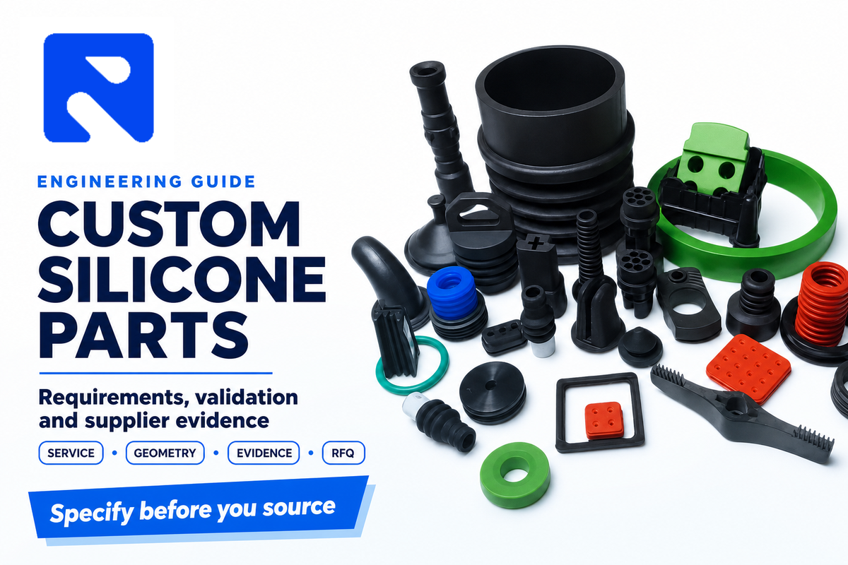
The question shouldn’t be, “Can this feature be molded?” The right question should be whether the chosen material, process, tool, metrology, and evidence can show the part will function in the specified service.
Teams specifying silicone products can use this guide as a shared end-to-end path through product development across engineering, quality and purchasing. It includes various topics such as process selection, part shape, manufacturing processes, tolerances, prototypes, supplier evidence, cost drivers, and the RFQ package. This article is limited to requirements, validation, and evidence planning before supplier selection.
Start With the Service Conditions, Not a Silicone Grade
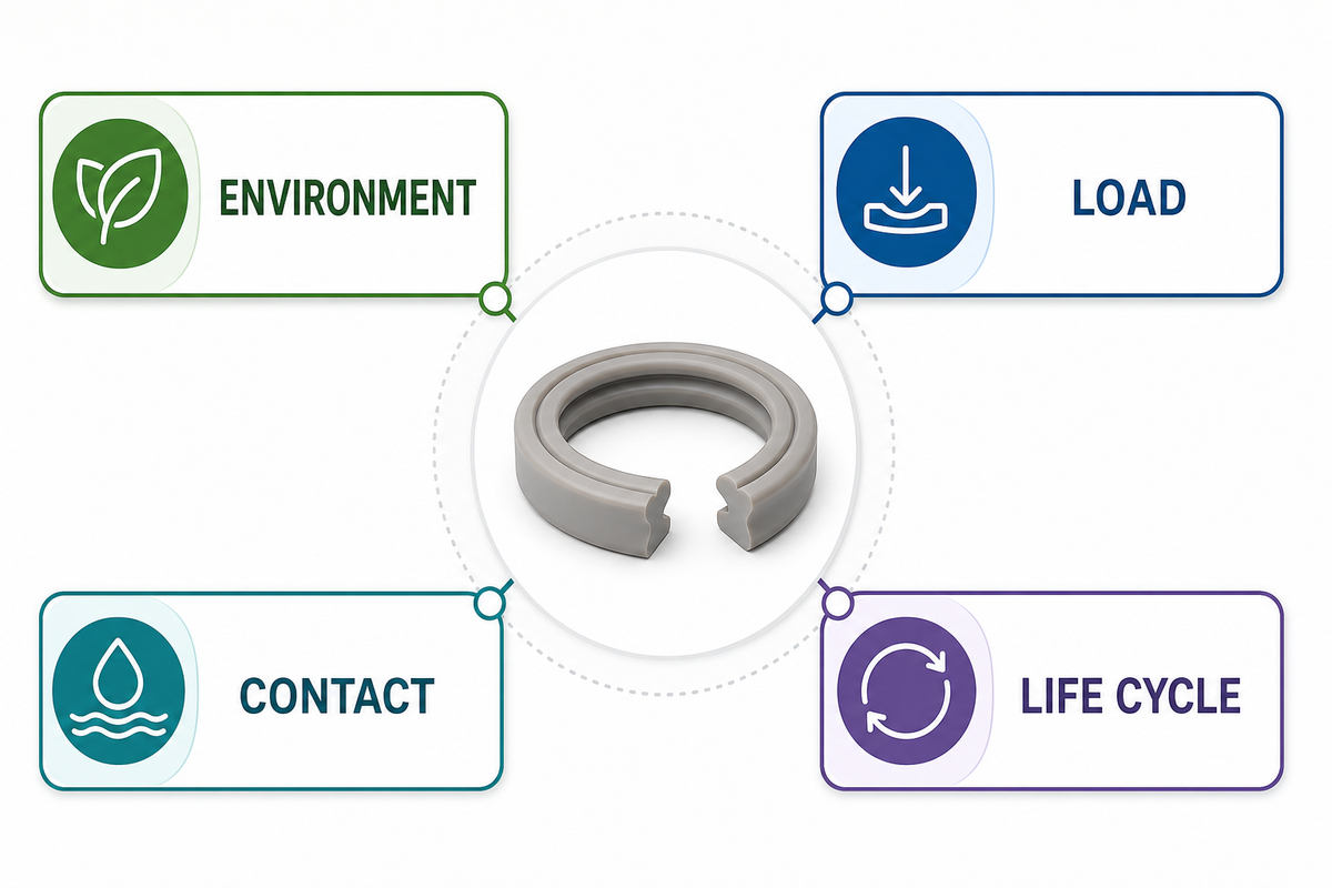
“Silicone, 50 Shore A” is not a complete performance specification. ASTMD2240 describes durometer hardness as an empirical control test; it does not create a simple relationship to a fundamental material property. Hardness may help control a silicone mixture, but it may not replace high-temperature or other application requirements.
Begin with six input groups:
- Function: Seal, valve, diaphragm, grip, insulator, protective boot, fluid path or cosmetic interface.
- Environment: continuous and peak temperature, fluids, cleaning agents, UV, ozone, pressure, vacuum, and sterilization or wash cycles where relevant.
- Interfaces: mating geometry, compression or deflection, surface condition, insert materials, and assembly loads.
- Life: static duty, cycle count, storage time, maintenance interval, and acceptable drift.
- Controls: restricted substances, color, cure system, cleanliness, traceability, and any market-specific regulatory obligations.
- Demand: prototype quantity, launch quantity, annual volume, lot pattern, forecast uncertainty, and service-spares requirement.
Assign an owner to each item. Functional limits and interfaces should be owned by engineering. Acceptance methods and records should be owned by quality. The demand profile and commercial comparison should be owned by purchasing. Molders should confirm manufacturability and identify variables that depend on material, tooling, and equipment. An unresolved input shouldn’t be automatically considered a supplier decision; this division of responsibility keeps custom silicone rubber parts requirements tied to evidence.
Practical checkpoint: If two suppliers are quoting materially different parts and claiming to follow the same RFQ, the requirement isn’t ready.
Document Manufacturing Route Constraints From Geometry, Volume, and Control Needs
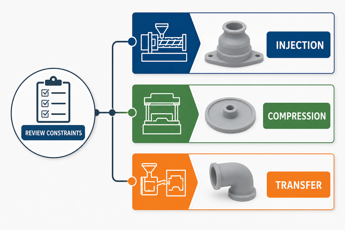
For custom molded silicone components, process selection is a boundary decision and should eliminate routes such as silicone injection molding when they can’t produce the needed geometry or evidence prior to comparing costs. No universal annual volume cutoff can determine this, because cavity count, cycle time, scrap risk, automation, inspection, and tool concept change the economics.
| Tipo di processo | Often fits | Main strength | Watch first |
|---|---|---|---|
| Stampaggio ad iniezione LSR | Complex three-dimensional parts, thin features, repeat production, overmolding | Automated metering and repeatable cavity filling can support scale | Tool precision, flash control, gate/vent strategy, cure, and demolding |
| Stampaggio a compressione | Some thicker or simpler molded geometries and programs where a different tooling approach is useful | Broad compound and geometry options | Charge placement, flash, labor content, cycle, and dimensional strategy |
| Stampaggio transfer | Molded geometry where a transfer pot and runners suit the compound and tool concept | Controlled transfer into closed cavities | Material waste, runner design, pressure, and insert movement |
| Estrusione | Continuous profiles with a stable cross-section | Efficient length production | Cross-section limits, cut length, joints, and secondary operations |
| Die cutting | Flat gaskets, pads, and sheet-derived shapes | Simple tooling for suitable two-dimensional parts | Thickness availability, edge condition, adhesive, and material utilization |
| Waterjet or knife cutting | Flat sheet parts, development quantities, or shapes that do not justify a dedicated die | Flexible profile changes | Edge quality, kerf, thickness, speed, and repeatability |
| RTV casting | Low-quantity learning parts and shapes suited to casting | Fast design learning in selected cases | Production representativeness, material differences, bubbles, cure, and dimensional repeatability |
| Additive pattern or soft-tool prototype | Form-and-fit learning before production tooling | Short feedback loop for geometry | Material, surface, tolerance, and process differences |
| Insert or overmolding | Silicone integrated with metal parts or suitable plastic parts | Fewer assembly steps and retained inserts | Mechanical retention, adhesion, insert position, and cure temperature |
For LSR, suppliers’ design rules are capability-specific and don’t follow universal material laws. Protolabs, for example, specifies limits for wall thickness, draft, and undercuts, and recommends part size. These shouldn’t be copied to a drawing as if they represented the limits of the entire manufacturing universe. For comparison, see Engelhardt’s guide to stampaggio a compressione rispetto allo stampaggio a iniezione.
How do geometry, annual volume, and quality requirements change the choice?
For molded components, geometry establishes feasibility: Shape and dimensions of features may eliminate a design route because of cross-sectional areas, shut-offs, undercuts, inserts, and parting lines. Volume establishes the economic window, but only after the tool concept and production assumptions are aligned. The design may require certain properties and/or evidence of compliance. The evidence of compliance may require additional inspections, automated handling, lot traceability, or high inspection coverage, which in turn may require different tooling and processes than a visually similar low-volume part.
When should molded silicone lose to another method?
Continuous profiles are typically suited to extrusion. Die cutting is often suited to 2D sheets that meet functional and edge requirements. Consider RTV silicone casting for learning or low-quantity applications only when the differences between the material, process, and what is being tested do not undermine the case being presented. If the prototype must validate production shrink, flash, cavity-to-cavity behavior, or production-intent material, a non-production route may answer the wrong question.
Turn Geometry Into Moldable, Inspectable Features
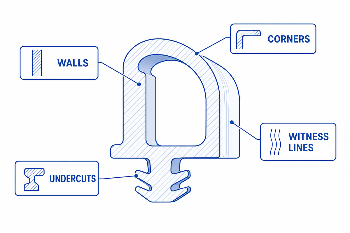
For molded parts such as an O-ring or other sealing parts, a DFM review should follow the path of material and the path of part removal. Start at the gate or charge, follow filling through thin sections and around inserts, locate trapped air, then examine every shut off and parting line. Also review undercuts and retention features, then consider how an inspector will find and support a flexible part. Engelhardt’s guida sovrastampaggio offers related context when a silicone and rubber component meets an insert or substrate.
Review these items explicitly:
- Abrupt wall-thickness changes can create unwanted variation in flow, cure, cooling, and local stiffness. Designers should balance those effects against the part’s functional requirements.
- Parting and shutoffs: Place unavoidable witness lines away from critical sealing, optical, hygienic, or cosmetic surfaces.
- Vents and flash: Define edges to be functionally critical and describe how excess material will be constrained or removed.
- Undercuts and demolding: Flexibility can help during removal, but strains may damage or deform part features.
- Inserts and overmolding: State insert material, surface condition, retention method, positional control, and bond requirements.
- Datums and fixtures: Help the supplier to position the tool and the part in a stable condition for inspection.
Separate supplier capability statements from design requirements. An unrelated page stating that a molder can form a thin wall doesn’t prove that your wall can be filled next to a thick boss, released without damage, and measured consistently. Ask your supplier for a DFM record for the part in question which identifies assumptions and questions, and indicates drawing changes.
Specify Tolerances by Function and Measurement Method
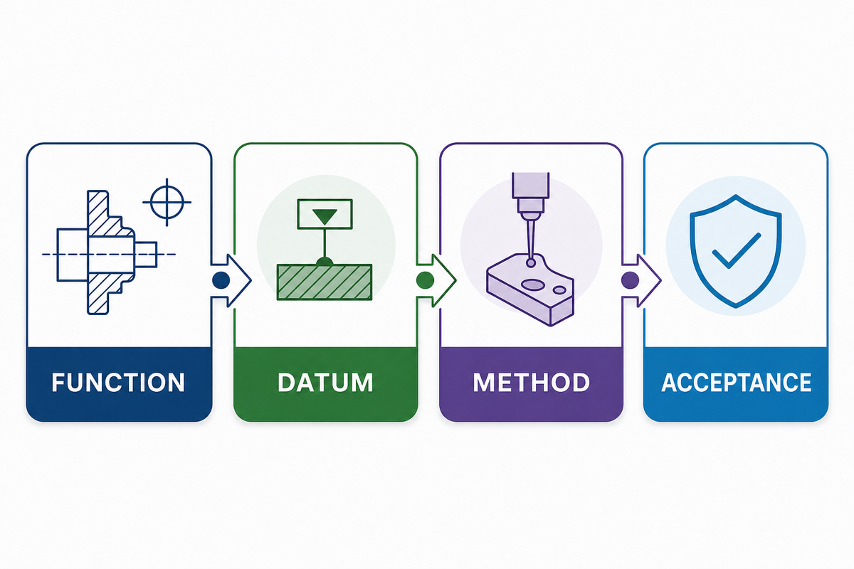
Elastomers deform under their own weight and under contact from fixtures and measuring tools. A dimension without conditioning, support, measurement force, and timing can produce arguments rather than control.
ISO 3302-1:2014 provides dimensional-tolerance classes and test methods for molded, extruded, and calendared solid rubber products, and ISO confirmed that edition in 2024. Its companion ISO 3302-2:2022 addresses geometrical tolerances. These are frameworks, not permissions, to assign tight tolerances or a custom size limit to each feature. Determine which dimensions are fixed by a single mold component and which depend on mold closure, parting, or other process relationships. Then negotiate the applicable class and exceptions with the molder. The site’s rubber molding tolerance guide is useful background for that supplier discussion.
| For each critical characteristic, record | Perché è importante |
|---|---|
| Functional reason | Prevents cost being added to noncritical dimensions |
| Datum and restraint | Controls how a flexible part is located |
| Conditioning and measurement timing | Separates transient post-mold behavior from acceptance |
| Instrument, fixture, and contact force | Makes results reproducible between buyer and supplier |
| Sampling and reaction plan | Defines what happens when a result approaches or exceeds a limit |
If a collection of dimensions defines a feature more than any single dimension does, then use a profile, fixture check, or functional gauge to verify the feature. Separate cosmetic limits, flash limits and surface discontinuities from dimensional limits to give each their own acceptance criteria.
Build a Prototype and First-Article Plan That Represents Production Risk
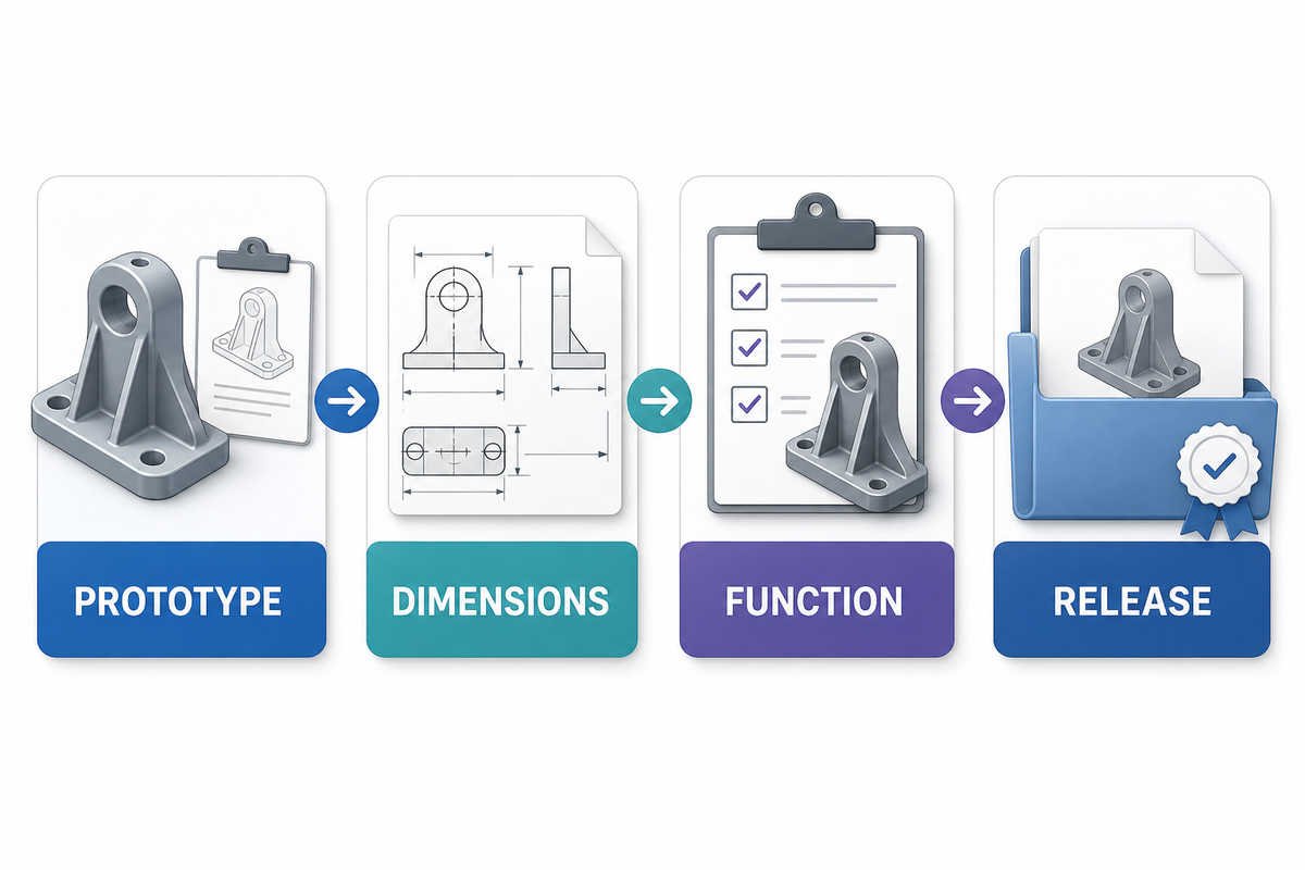
Evaluation of a prototype should consider the answers to the questions presented by the materials and processes involved, including the process-specific constraints in LSR design guidance. A cast part may provide evidence for envelope, assembly access, and ergonomics, and may suggest an assembly sequence. However, it usually can’t provide evidence for production-cavity flash, production-cure, automated handling, cavity balance, or control of materials at the lot level.
- Learning model: Verify shape, interfaces, and assembly sequence, and identify any deliberately nonrepresentative properties.
- Production-intent sample: Use the intended material family and a representative process to evaluate the key product risks.
- Tool trial: Check gates, vents, parting lines, flash, demolding, condition, and critical dimensions, based on documented settings.
- First article: link results to the controlled drawing, model, material, cavity or tool, process revision, and inspection method.
- Release lot: Confirm sampling, nonconformance handling, packaging, identification, traceability, and change notification against documented acceptance procedures.
Do not let “sample approved” imply one undifferentiated decision. Approve appearance, dimensions, material evidence, functional testing, and production release separately.
Once these requirements are controlled, review Engelhardt’s custom silicone parts manufacturing capabilities for the separate commercial and manufacturability discussion.
Request Evidence Before Tooling and Mass Production
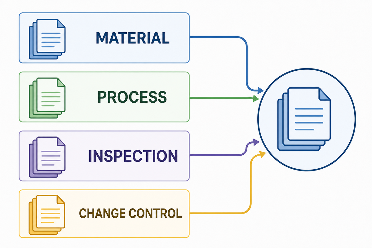
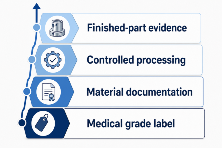
A certificate or title doesn’t mean proof for your part. Before tooling, ask what each document covers, who issued it, whether it is current, which of the materials used in the part it identifies, and how it will link to your drawing revision, material batch, tool, cavity, and production lot.
Use a requirements-to-evidence ladder:
- Requirement: the measurable or reviewable condition on the controlled specification.
- Method: test, inspection, review or control by the supplier.
- Owner: buyer, supplier, material producer, or independent laboratory.
- Record: report, certificate, data set, image, or approval.
- Linkage: revision, lot, cavity, batch or serial number, and date.
- Reaction: containment, disposition, corrective action, and change notification.
For regulated or safety-relevant applications, have qualified regulatory counsel or the responsible compliance team define the requirements for your finished product. Review the FDA’s explanation of food-contact substance oversight to understand the concept of intended use and regulatory scope. Material declaration or supplier quality certificates do not automatically validate that the finished product complies with requirements when placed on the market.
What should be reviewed before the tool is released?
Review the approved models and drawings, DFM assumptions, material and color constraints, tool ownership, cavity identification, critical characteristics, first article, test responsibility, sample size, change rules and acceptance authority. If a claim depends on a laboratory test, agree on specimen type, conditioning, method edition, and pass/fail rule before samples exist.
Normalize the Cost Drivers Without Asking for a Universal Price
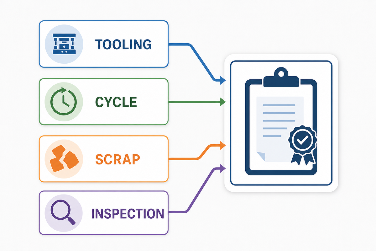
For custom rubber parts, cost drivers include tooling, cavity count, parting complexity, inserts, material controls, cycle time, labor, scrap, inspection, validation, packaging, and forecasting. A low unit price can hide a different tooling life, inspection plan, material scope, or change-control obligation. The same cost logic applies to a rubber molded item and is presented in Engelhardt’s custom rubber molding cost guide.
Normalize quotations before comparison:
- same controlled files and revision;
- same material and color-control scope;
- same tool ownership, cavity assumptions, and maintenance responsibility;
- same first-article and validation deliverables;
- same inspection, traceability, and documentation scope;
- same annual volume, order pattern, packaging, and delivery basis;
- same treatment of engineering changes, requalification, and end-of-life spares.
Then compare total program exposure, not only tool price and piece price. The cheapest quotation isn’t comparable if it doesn’t contain information required for release of the product.
Prepare an Evidence-Ready Silicone-Part Specification
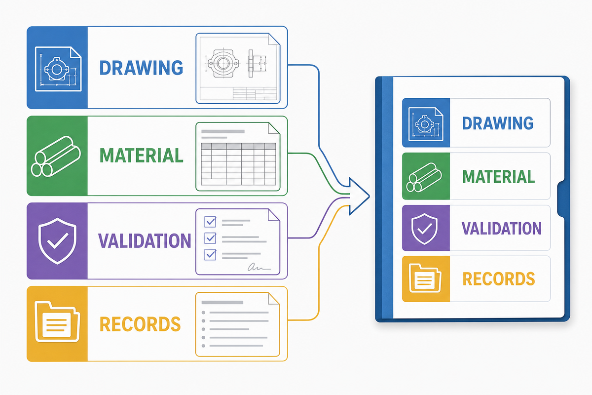
Each bidder, including a rubber parts manufacturer, must receive the same technical and commercial requirements, including the applicable rubber dimensional-tolerance framework, defined inspection methods, and production methods. Complete this checklist before sending the request for quotation.
- Required are controlled 3D models and drawings with revision and precedence of conflicts.
- Part function, mating interfaces, and service environment
- Required are material family, hardness method, color, and cure or restricted-substance controls where required.
- Critical-to-function dimensions with datum and measurement conditions
- Parting, flash, gate, vent, cosmetic, cleanliness, and packaging expectations
- Prototype, tool-trial, first-article, and release-lot quantities
- Annual forecast, order pattern, ramp, and spare-parts expectations
- Functional tests, specimen definition, method, owner, and acceptance rule
- Material, inspection, traceability, and change-control records
- Tool ownership, maintenance, storage, cavity identification, and transfer terms
- Quotation exclusions, open assumptions, and requested DFM response format
For a non-standard part, ask suppliers to include an assumption register with their quote. Sometimes it’s better to get a price with explicit exceptions than to get a clean price built on tacit assumptions.
What Is Changing in Silicone-Part Sourcing?
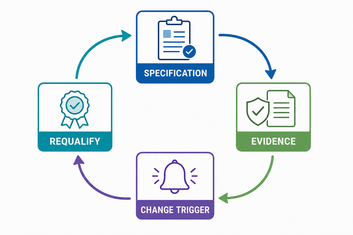
For buyers, the useful sourcing principle is not a market-size forecast. It is the need to make evidence portable across material, tooling, and supplier changes; primary material publications such as Wacker’s silicone technical guide help teams retain precise material and process terminology. Teams need to understand what will survive a material change, tool repair, cavity addition, supplier change, or regulatory review. A drawing without a method or record of ownership is difficult to transfer.
Treat traceability and change visibility as design inputs. Define early what will be the minimum record set, so claims can be tied to evidence. Making requalification conditions and triggers explicit reduces the chance that a commercially simple supplier change becomes a technical rediscovery project.
Keep Material and Process Terms Precise and in Scope
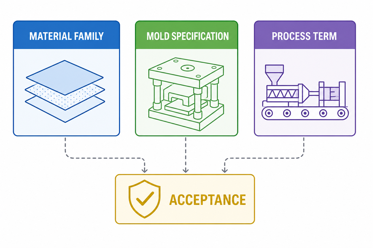
Material families, silicone mold specifications, silicone moulding terminology, fabrication methods, and manufacturing routes are not interchangeable; material consistency must be specified separately. Primary silicone technical guidance distinguishes liquid silicone rubber, RTV systems, and solid silicone rubber; pair the selected family with a defined process, vulcanization or cure control, service condition, inspection method, and acceptance criterion.
Domande Frequenti
Are custom silicone parts always made by injection molding?
No. LSR injection molding is one route, but compression molding, extrusion, die cutting, and RTV casting can be appropriate for different geometries, volumes, and learning goals. Select the route after defining cross-section, three-dimensional features, inserts, evidence requirements, production pattern, and acceptable tooling assumptions. A process name by itself doesn’t establish approach suitability.
Is a Shore A value enough to specify silicone?
No. Specify the service condition and required evidence, then use hardness as one controlled property within a fuller material specification. Shore hardness is a useful control measurement, but it does not define temperature behavior, fluid compatibility, compression behavior, tear performance, cure system, color, cleanliness, or regulatory suitability.
Can prototype silicone parts validate production tolerances?
Only when the prototype material, tool, process, conditioning, and measurement method represent the risk being evaluated. A cast or soft tool sample may validate form and assembly and fail to represent production flash, shrink, or cavity balance, and cure. State which risk each prototype is authorized to answer.
What usually drives custom silicone tooling cost?
Geometry, tool construction, cavity count, parting and shutoff complexity, inserts, gating and venting, flash-control needs, automation, material controls, inspection, and validation scope all matter. Typically, a bid is dependent on how your scope items align. Tooling that appears less expensive may also represent a lesser scope.
What should be approved before a production tool is released?
Approve the controlled design, DFM assumptions, scope of material, critical characteristics, measurement methods, tool concepts, first article plans, test ownership, traceability, change notifications, and acceptance authority. The release should show what’s fixed, what’s supplier-defined, and what evidence is required before mass production.
Conclusione
A strong requirements-and-validation package reduces ambiguity before supplier selection. Define service conditions, process constraints, inspection methods, record ownership, and acceptance evidence first. When the package is ready for manufacturing review, continue to Engelhardt’s custom silicone parts manufacturing page for commercial scope and quotation support.
Riferimenti e fonti
- ISO 3302-1:2014, Rubber dimensional tolerances
- ISO 3302-2:2022, Rubber geometrical tolerances
- ASTM D2240, Durometer hardness test method
- FDA, How food-contact substances are regulated
- Wacker, Solid and Liquid Silicone Rubber
- Protolabs, LSR molding design guidelines (supplier-specific example)
Confirm the standards, editions, methods, regulations and supplier limitations that are applicable to the program.