Get in Touch with Engelhardt

Silicone Compression Molding — Custom Molded Silicone Parts | Engelhardt
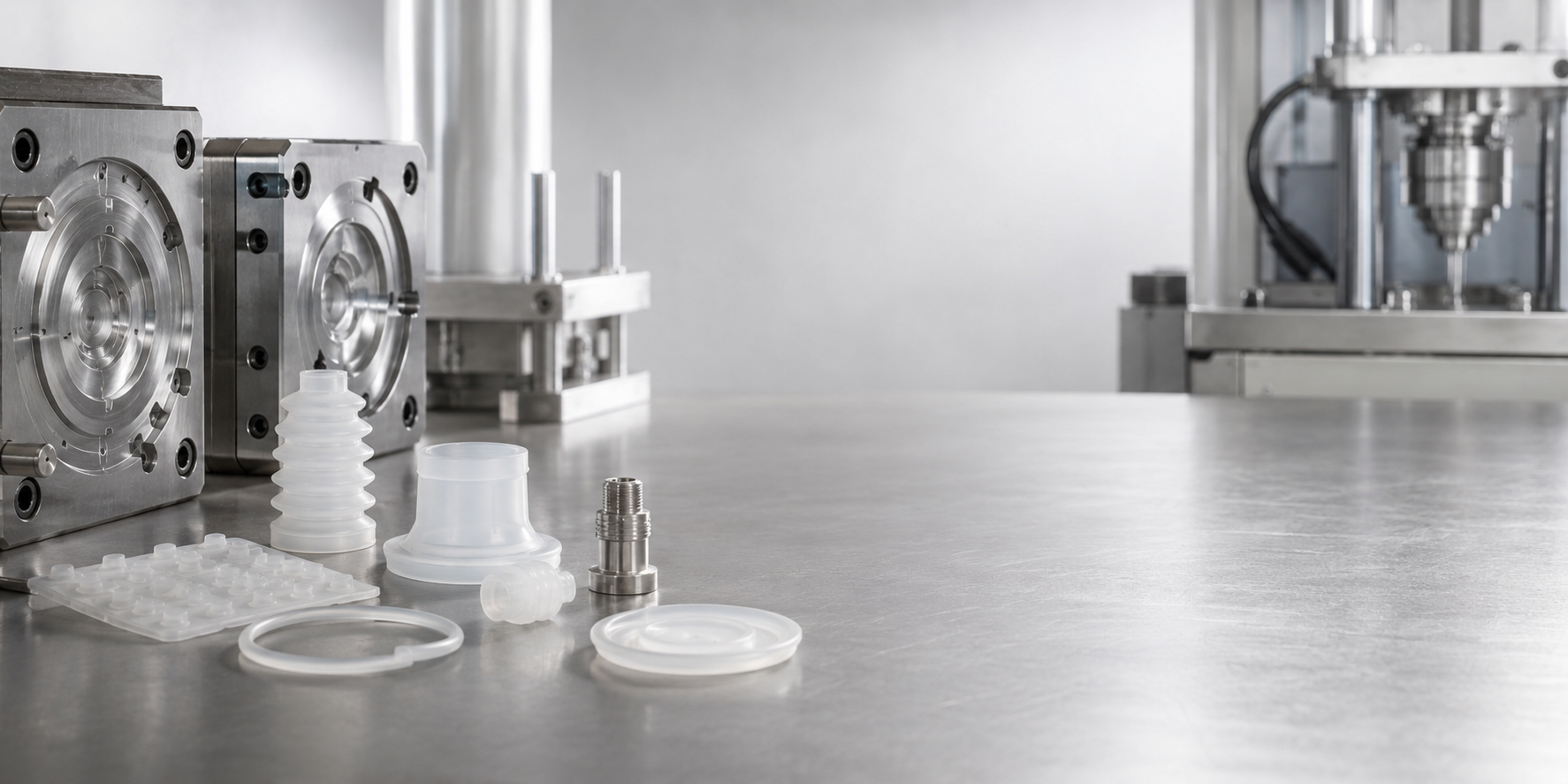
With this simple, yet robust process uncured HCR silicone can be shaped into finished gaskets, seals and molded silicone components using heat and pressure – and its the choice of supplier who determines tolerances, flash free production and delivery to schedule! Cell team Engelhardt runs this process in-house on 80+ vulcanizing presses, supported by a ISO 9001 quality system: IATF 16949.
[DATA-MATRIX] SPECIFICATIONS
80+
Vulcanizing / compression presses
50–300 t
Press tonnage range
M1–M2
ISO 3302-1 tolerance class
20–80
Shore A durometer range
17 yrs
Silicone & rubber molding
ISO 9001 · IATF 16949
Certified quality system
02 /
ENGINEERING ASSESSMENT
Why Compression Molding Fails With the Wrong Supplier — and How Engelhardt Solves It
Buyers do not usually lose money doing the actual process of compression molding. They do so on a vendor who over-produces the tool, hand-trims the flashing unevenly, or quotes a price that includes “hidden” re-work. A silicon component that appears correct on the initial sample can run out of tolerance by the third batch.
The defect engineers raise most often
The ageless warning about compression molding on manufacturing forums is that if parts are badly controlled “small cold seams can be created which trap bacteria”—a realistic issue for medical and food-grade contact silicone parts. Coldseaming occurs when uncured silicone is improperly placed in the mold cavity or when the dwell time (pressure and heat application) isn’t sufficient to cure the charge thoroughly. The solution is not luck; it is slug weighing, cavity placement and an approved cycle profile.
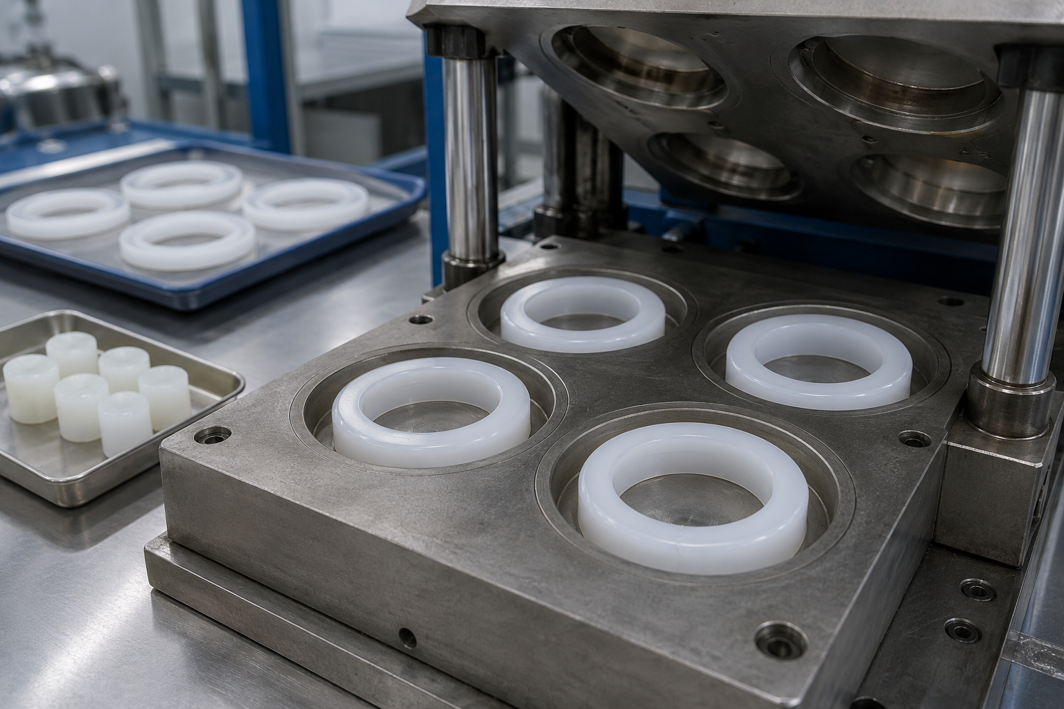
Silicone rubber compression molding—known in markets using British-spelling as compression moulding—injects a pre-weighed amount of uncured silicone into each half of a heated mold. Clamping the tool applies the heat and pressure that cures the product to the shape of the cavity. When done correctly, this method is ideal when making items like gaskets, seals and thicker cross-sections at low-to-medium volume.
[CRITICAL CONTROL MATRIX]
-
01
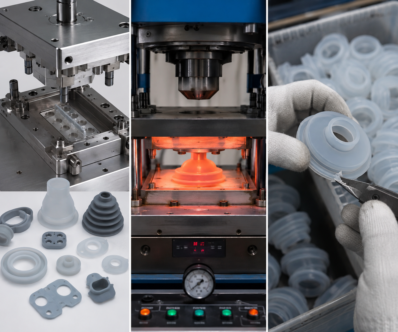
Mold design and tooling
Parting line, vent design and cavity balance determine flash thickness and fill and, a weak compression mold will never give a clean silicone component.
-
02
Cure discipline
Temperature, dwell time and pressure need to be compliant with the silicone compound because curing too fast is at the root of cold seams and high compression set.
-
03
De-flashing control
Each compression mold component has parting-line flash, and its method of removal requires all edges remain consistent over 20,000 parts.
03 /
FACILITY OVERVIEW
Engelhardt’s Silicone Compression Molding Capabilities — Presses, Materials & Tolerances
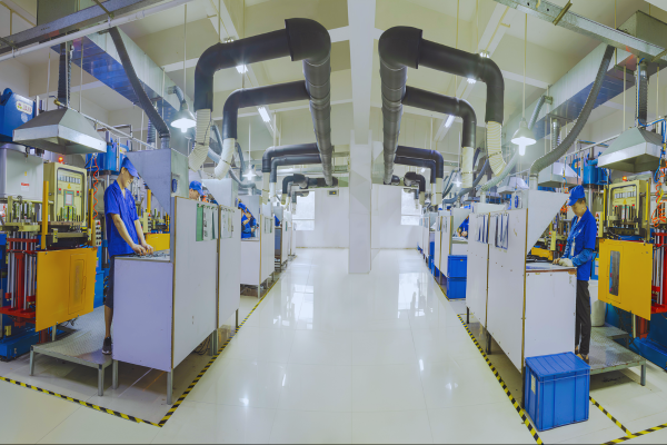
Engelhardt has a manufacturing facility where rubber and silicone parts have been made since 2009. Currently, the silicone compression molding is utilizing a new workshop apart from the standard silicone manufacturing factory.
In the company we have over 80 vulcanizing presses with their own mold designing and tool making works. The yearly production of silicone parts is about 1000 tons. The tooling is just part of the high quality silicone part – the discipline around it is what makes this possible.Engelhardt supplies each press with documentation, cure schedules, in process checks and de-flashing lines commensurate to the part, so that Silicone Rubber Molding output is reliable from first article to final lot.
Tolerance reference — ISO 3302-1
Dimensional tolerance of a compression silicone molded part is governed by the ISO 3302-1 standard, which lays out four classes from M1 (precision) to M4 (general). For a fixed dimension of 10-16mm, Class M1 permits 0.15mm, Class M2 permits 0.20mm, and Class M4 permits 0.80mm. Hardness tolerance is ± 5 Shore A from nominal. We specify an achievable class for your compression molded silicone part before tooling is cut, not after the first article.
[DATA-MATRIX] SPECIFICATIONS
Vulcanizing presses
80+ across silicone & rubber workshops
Workshop machines
20+ presses incl. 250 t vacuum vulcanizing & 300 t press
Tonnage range
50–300 ton clamping force
Solid durometer
20–80 Shore A (HCR / HTV grades)
Service temp
−50 °C to +250 °C std; specialty grades to +300 °C
Dimensional tol.
ISO 3302-1 Class M1–M2 on precision features
In-house mold shop
3,600 m²; CNC, EDM, deep-hole drilling, high-speed machining
De-flashing
Automatic, frozen / cryogenic and hand trimming lines
Silicone Materials We Mold
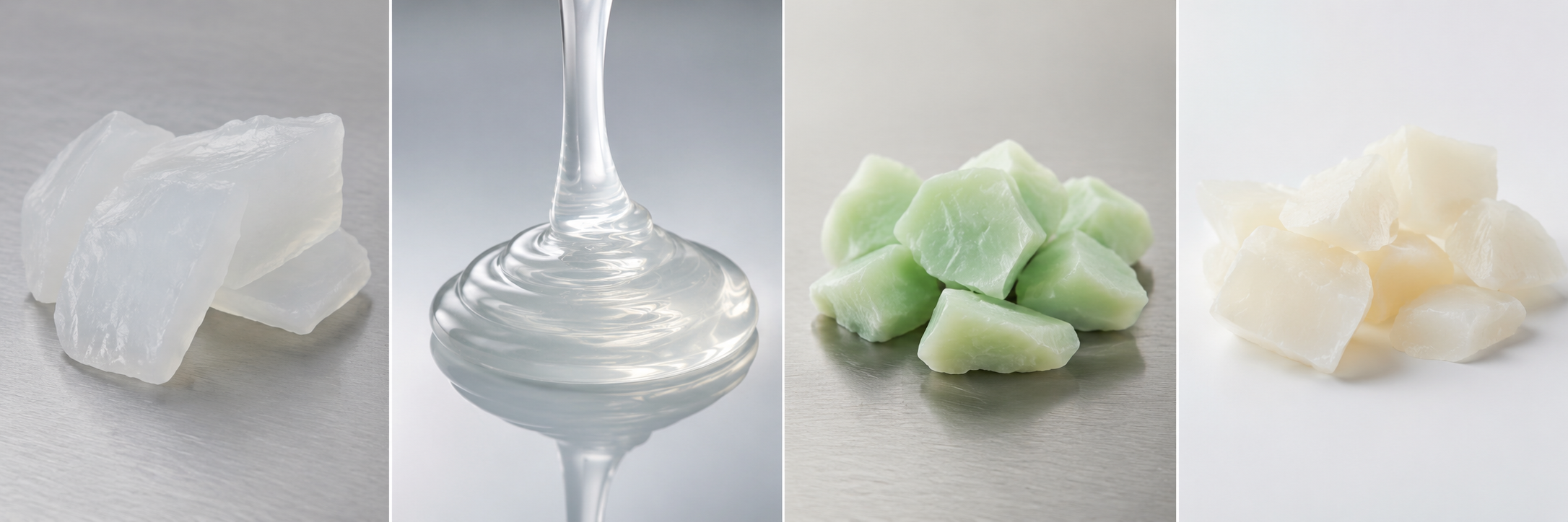
Compression molding uses solid silicone – High-Consistency Rubber (HCR), known as HTV (High-Temperature Vulcanizing) silicone. It is a gum-like raw material that cures when exposed to heat, unlike the 2-pack liquid silicone rubber used in injection molding. The grade of the silicone is a lifetime and tolerance decision, and should not be based on price.
| Material | Form & process | Durometer | Best-fit silicone parts |
|---|---|---|---|
| HCR / HTV silicone | Solid gum, compression & transfer molding | 20–80 Shore A | Gaskets, seals, thick-section parts, keypads |
| Liquid silicone rubber (LSR) | 2-part liquid, injection molding | 10–70 Shore A | High-volume, thin-wall, complex geometry |
| Fluorosilicone | Solid, compression molding | 40–70 Shore A | Fuel / fluid-resistant seals, aerospace |
| Food-grade silicone | Solid HCR, compression molding | 30–70 Shore A | Kitchenware, food-contact gaskets |
Process & Material Selection Matrix
The biggest cost in custom silicone molding is selecting the process after the tool is built. This process selection matrix aligns your project for the correct molding process prior to any tooling expenditure, so volume, cost and complexity are aligned.
| If your project is… | Recommended process | Why |
|---|---|---|
| Under ~5,000 parts, simple-to-medium geometry | Silicone compression molding | Low tooling cost; fast to first article |
| Thick-walled or large cross-section parts | Compression molding | Even cure through heavy sections |
| High volume, thin-wall, fine detail | LSR injection molding | Short cycle time amortizes higher tooling |
| Parts with metal inserts / encapsulation | Transfer molding | Closed mold protects insert position |
| Prototype or design-validation run | Compression molding | Inexpensive tooling, quick iteration |
04 /
MOLDING PROCESS BENCHMARKS
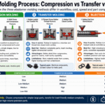
Compression vs. LSR Injection vs. Transfer Molding — A Data-Driven Comparison
“Which molding process is cheapest” is position dependent – it will change with volume. Compression molding wins when tooling costs and cycle time are compared at low volume; injection molding wins as volume grows, and the overall time saved. The chart below demonstrates the industry reference benchmarks that should be part of your decision making process before committing to tooling.
Actually, below roughly 5,000 parts, compression molding brings the lower total cost because the tool is a great deal less costly to build. Above that, the reduced cycle time of injection molding begins to offset its tooling premium. Thick sections, high temp HCR silicone favor compression at nearly any volume.
Transfer molding sits midway between compression and injection. The silicone charge is preheated in a pot, then injected through runners into the closed mold – making this compression moulding variant suitable when a part with metal inserts needs to stay put during fill. It offers the low-pressure, more affordable tooling of compression molding without compromising fill on detailed cavities.
$1k–$20k
Typical silicone compression mold tooling, against $3,000-$100,000+ (grey, below) versus an injection mold production run. For low and medium volume, this tooling disparity is the defining factor in your overall cost of ownership.
Want the cost crossover modeled for your annual volume?| Factor | Compression molding | Transfer molding | LSR injection molding |
|---|---|---|---|
| Cycle time | 1–5 min | 2–5 min | 10–60 sec |
| Typical tooling cost | $1,000–$20,000 | $3,000–$25,000 | $3,000–$100,000+ |
| Economic volume | 50–5,000 parts | Mid-volume | 5,000–1,000,000+ |
| Part complexity | Low to medium | Medium, inserts OK | High, fine detail |
| Parting-line flash | Present — trimmed | Minor | Minimal |
| Material | Solid HCR / HTV silicone | Solid silicone / rubber | Liquid silicone rubber |
05 /
INDUSTRIES & RESULTS
Custom Molded Silicone Parts We Produce — Industries & Results
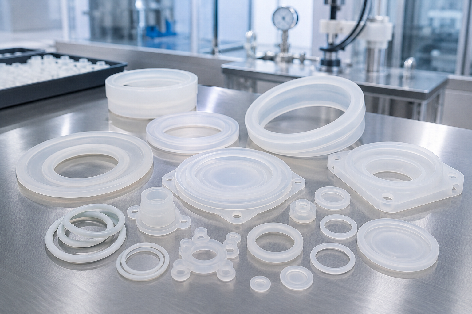
Silicone earns its place where other elastomers fail: it holds elasticity from 50 to +250, resists ageing and remains inert against the majority of chemicals. Engelhardt applies compression molding to that set of properties in six core part families.
[FAM-01]
Medical & lab seals
Gaskets, diaphragms and seals where flash control and food-/medical-grade compounds matter.
[FAM-02]
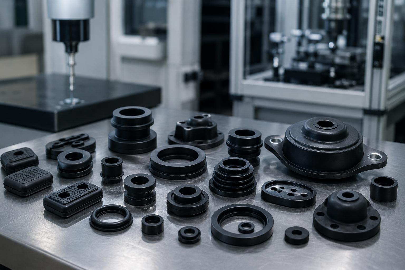
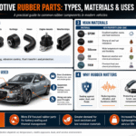
Automotive components
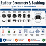
Vibration pads, grommets and seals molded under an IATF 16949 system.
[FAM-03]
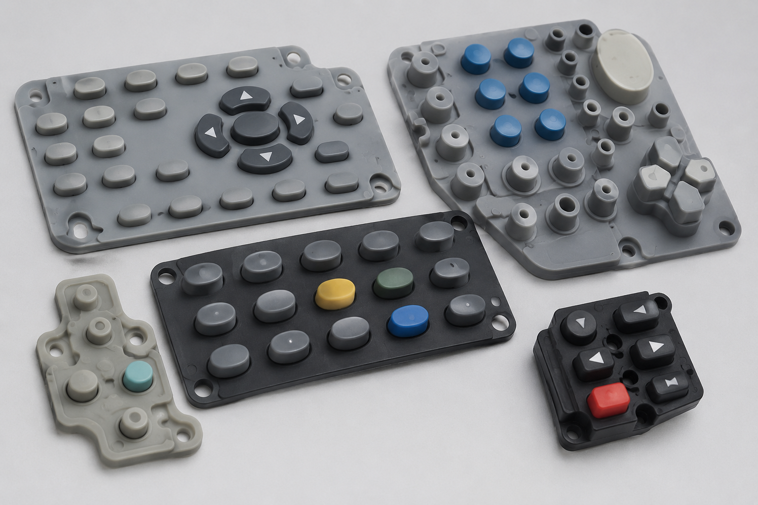
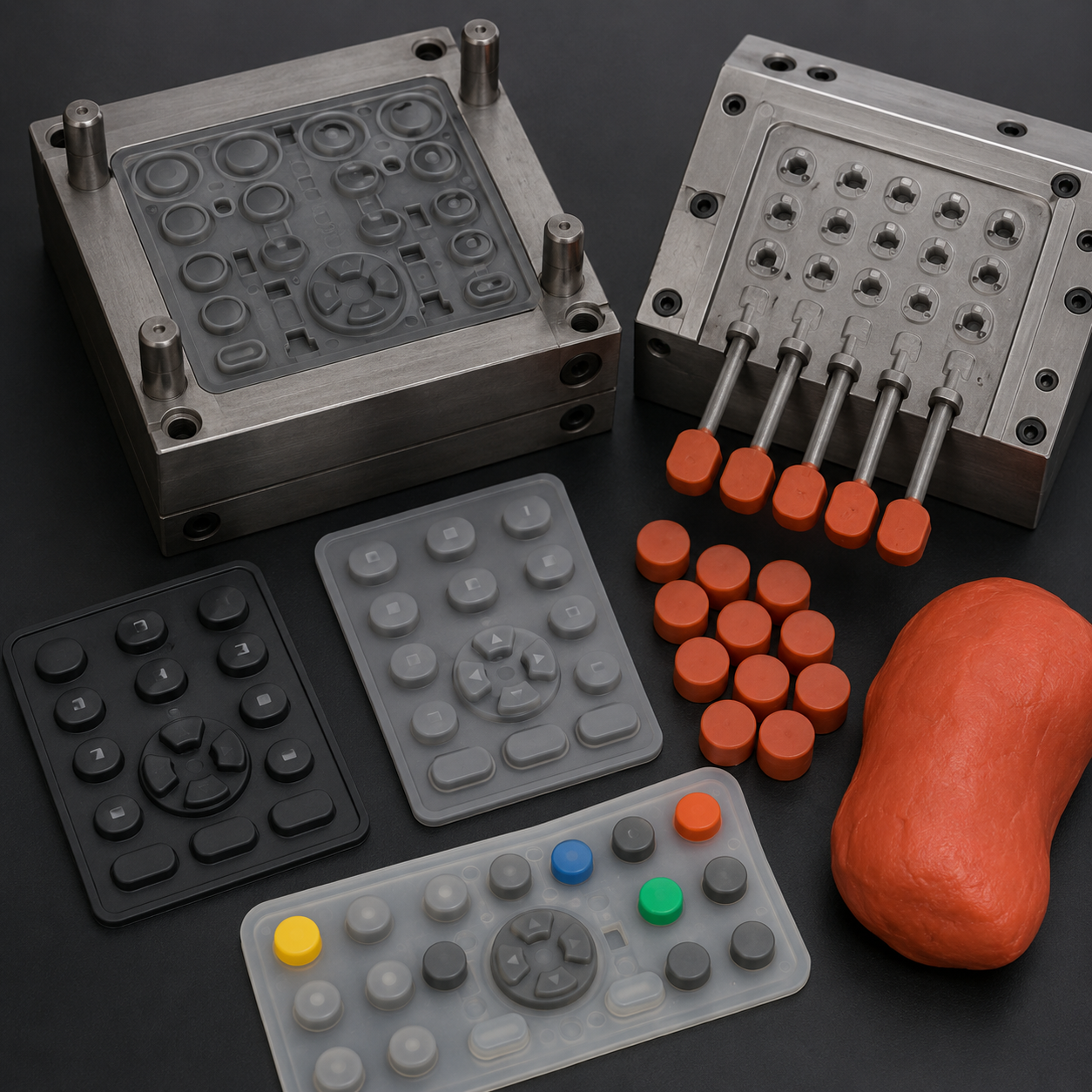
Silicone keypads
Compression-molded rubber keypads for instrument and industrial keyboards.
[FAM-04]
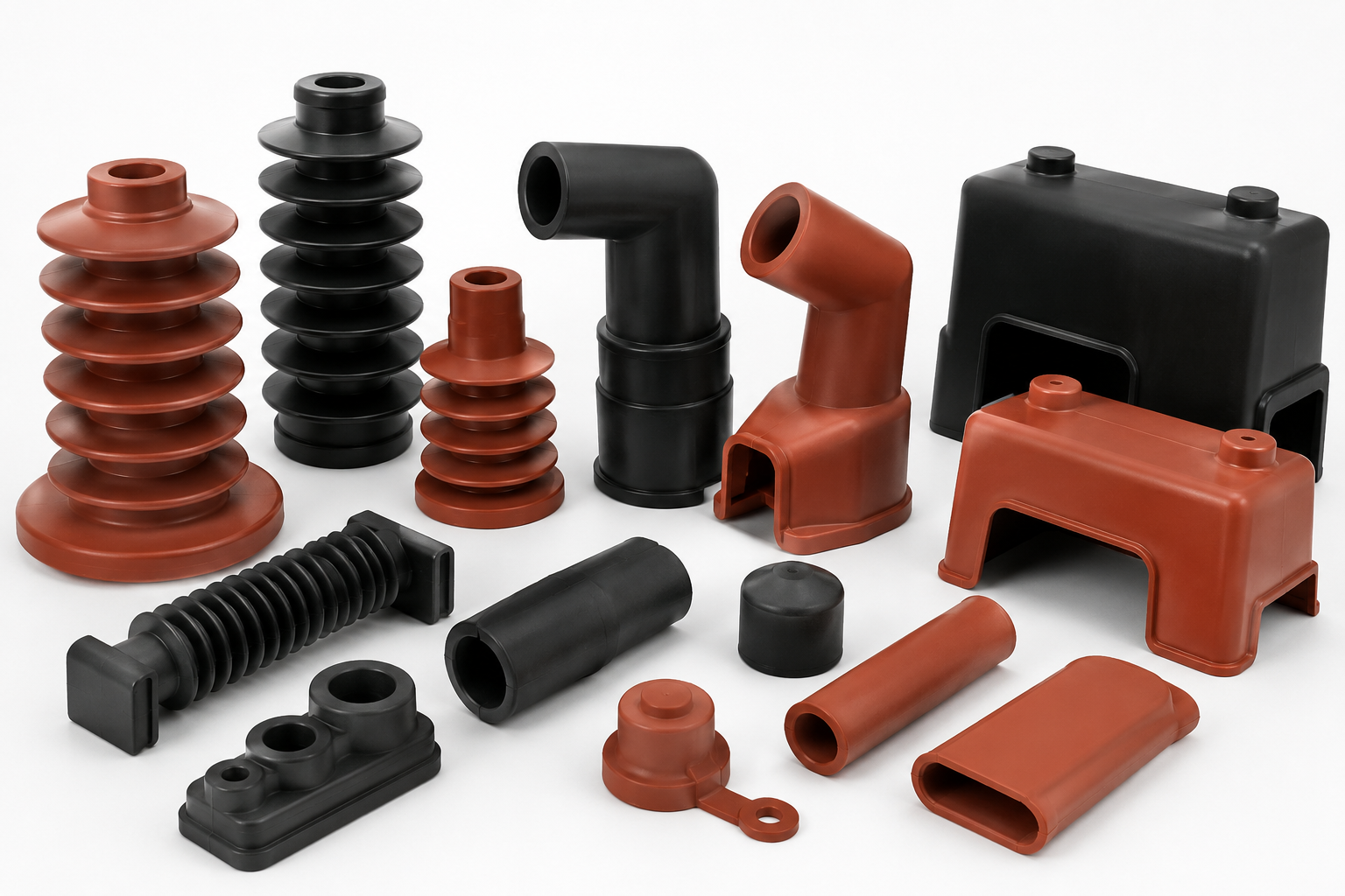
Electrical insulation
Insulators, switch boots and battery protective jackets.
[FAM-05]
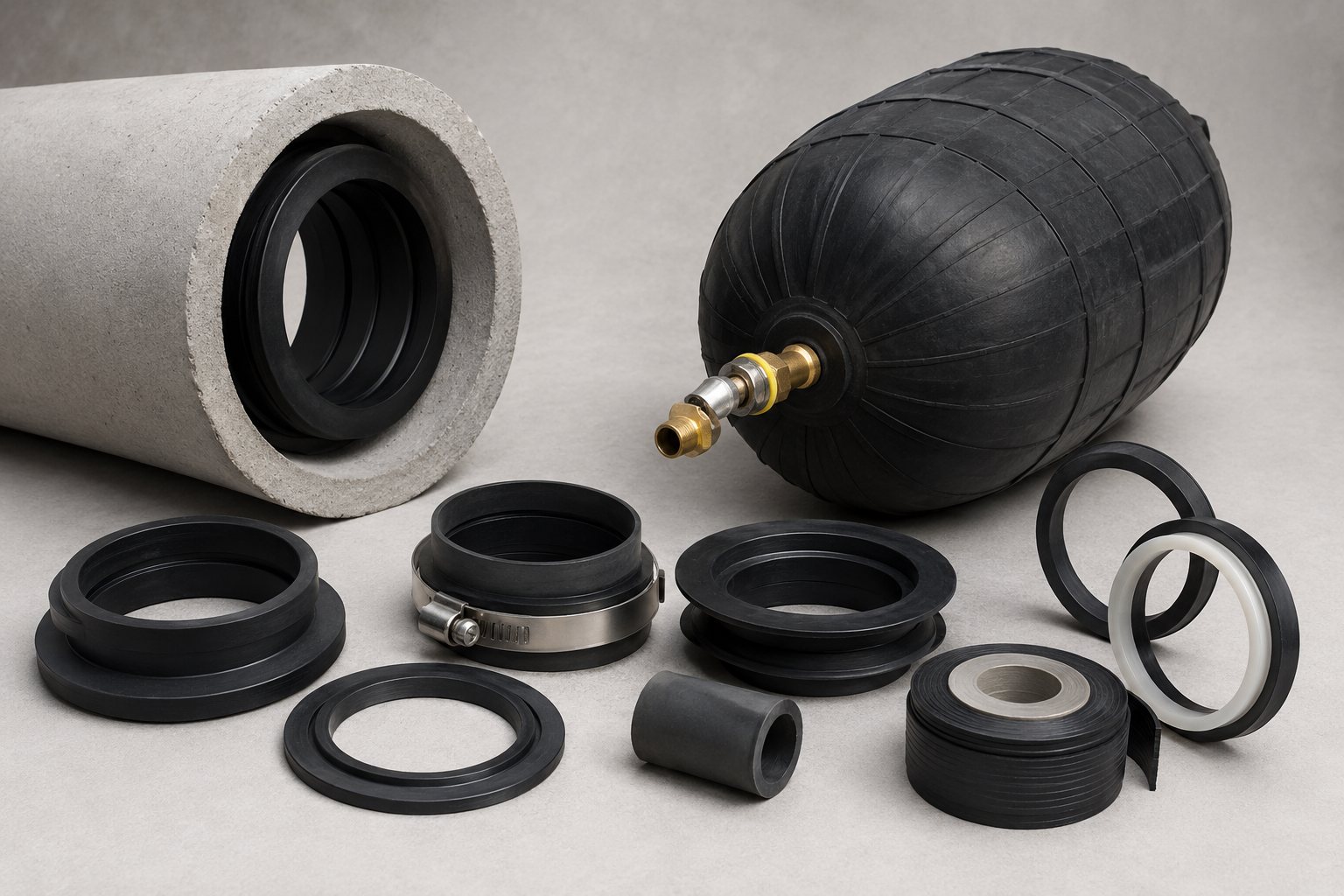
Sanitary & building parts
Pneumatic air bags, pipe-sleeve gaskets and plumbing seals.
[FAM-06]
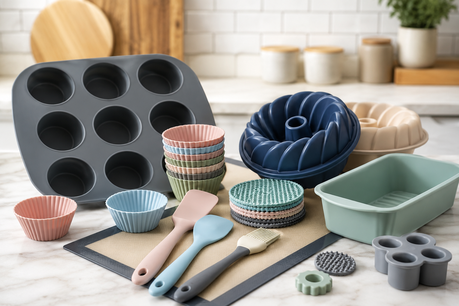
Kitchenware & consumer
Food-grade silicone bakeware and household molded parts.
These application examples highlight how the process decisions discussed above are applied to real part groups. Each is driven by a distinct customer constraint – tolerance, cost, or compliance. They reflect capability profiles rather than specific customer statements, so the engineering data supports the arguments made.
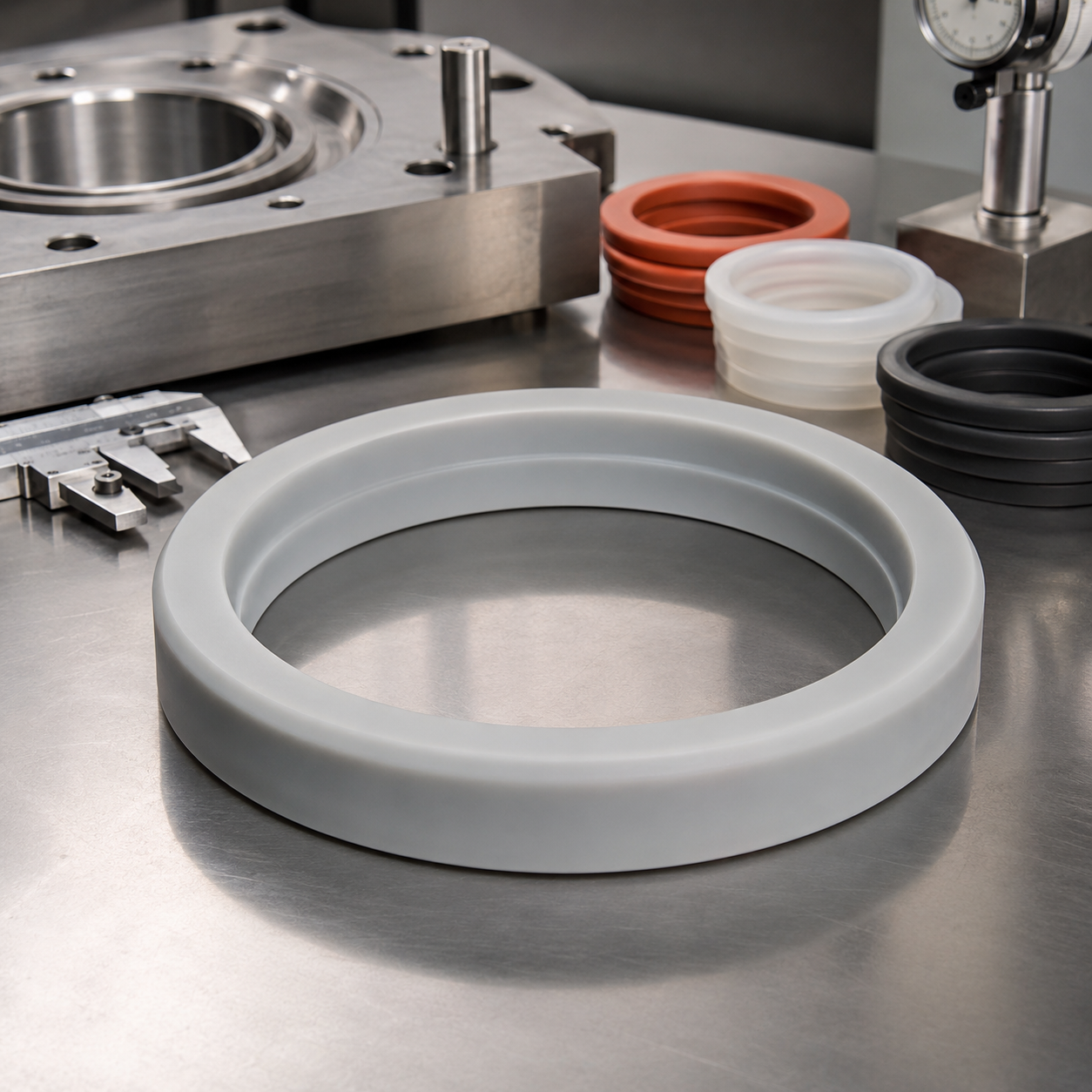
Application profile · Sealing
Thick-section gasket that injection molding struggled to cure
A silicone gasket with a heavy cross-section is unsuitable for injection molding – the massive wall heats up and risks creating an under-cured core. Compression molding volumes the entire silicone charge into the tool and maintains adequate heat and pressure for a complete cure to occur.
For these kind of pieces, Engelhardt can verify the cure profile using the actual compound production batch before tool-up, and measure the first-article’s hardness to ensure the seal is fit-for-purpose as a Class M2 part, or conventionally ‘finished.’
Application profile · Cost
Low-volume keypad program where injection tooling did not pay back
For a low-thousand keypad run, a steel LSR injection mold represents an investment that will never produce effective amortisation. A compression mold at a fraction of the cost deliver first-article production in 2-4 weeks and maintains a positive unit economics.
Slug weigh per cavity helps maintain fill, section by section, across a multi-cavity keypad tool – the parameter that can keep a run work, or flush unexpectedly.
Application profile · Compliance
Food-contact silicone part needing documented material traceability
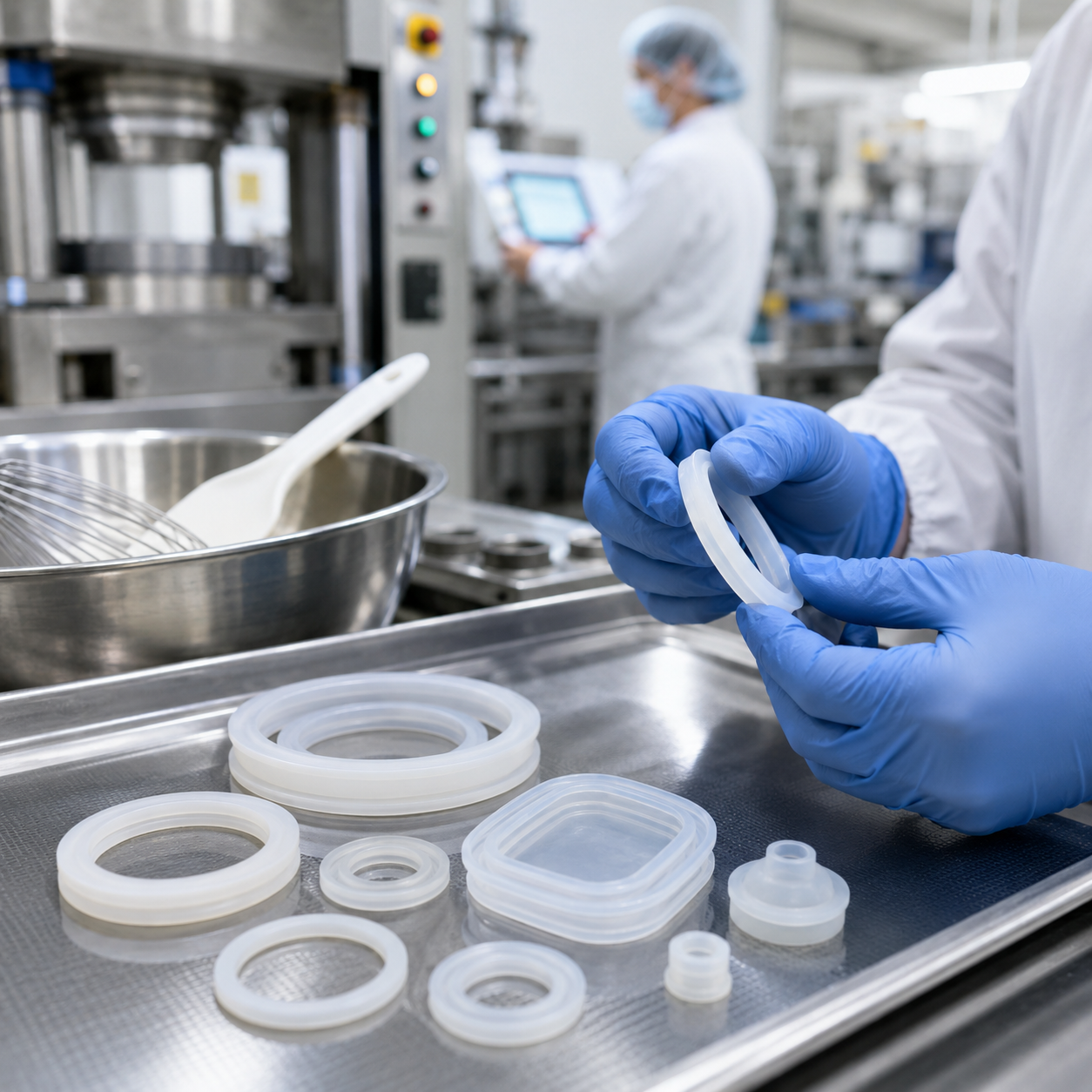
The buy-in for kitchen utensils and food-grade gaskets is not simply the part – it is also provenances for the compound. Engelhardt produces food-grade HCR silicone in a dedicated mold and traces back each batch through the MES/QMS system to material, press, and operator.
That information is what makes a compression molded silicone part an audit-ready part for the procurement team.
Prepared with a part drawing?
Receive a quote based on your annual volume
04 /
QUALITY SYSTEM
Certifications, Compliance & Full-Traceability Quality
Industry sourcing reviews reveal that a large proportion of buyers encounter a hidden compliance issue when working with overseas suppliers – certificates that don’t fully clarify scope, or don’t match the legal entity. We address that with clearly named certifications and an auditable quality system.
ISO 9001:2015
Quality management system
IATF 16949
Automotive quality system
High-Tech Enterprise
Guangdong Province
RoHS / REACH
Material compliance on request
Food-grade
Compounds for food-contact parts
[DATA-TRACING] ERP, MES, QMS & WMS
Certificates only become valuable if the parts they relate to can be proven. Since 2017, Engelhardt has used a fully integrated ERP, MES, QMS and WMS system covering every stage in the process.
- Each batch can be fully traced forward and back – to lot, operator, tools and step.
- All our processing equipment is backed by an in-house laboratory – with Mooney viscometers, moving-die rheometers, and salt-spray, humidity and heat-aging chambers – that are used to verify every compound.
- Process validation under rules laid out by ISO 9001/ IATF 16949 – proven cure profiles and inspection attributes stored in the MES, not on paper.
What to request before you place a compression molding order
Ask any Silicone Molding manufacturer for the certificate of compliance in the correct legal-entity name, a statement of material compliance for your application, and a first-article inspection report template. A supplier that can provide all three quickly is a supplier whose quality system is real.
Require compliance paperwork for your audit file?
05 /
SOURCING GUIDE
Sourcing Guide — Tooling Cost, MOQ, Lead Time & After-Sales
Most quoting disagreements in custom silicone molding are not centered on the unit price. They are centered on the omissions.
Published sourcing survey says: shop quotes frequently omit secondary operations, tooling reduction versus rework, certification costs—and that’s where the 30% price advantage stealthily vanishes.
These ranges are established industry standards—your number should reflect cavity count, part size, durometer, and compound. What remains constant is how Engelhardt speculates: the cost lines below are itemized as they appear in the quote—not uncovered later.
Tooling cost & lead time reference
| Tooling type | Typical cost | Tooling lead time |
|---|---|---|
| Simple silicone compression mold | $1,000–$5,000 | 2–4 weeks |
| Complex / multi-cavity mold | $5,000–$20,000 | 4–8 weeks |
| First-article samples + inspection | Quoted with tooling | 7–12 days |
| Production run | By volume & durometer | Confirmed per project |
Line items Engelhardt itemizes — so there is no hidden cost
- Tooling reductionA DFM review before cutting steel decreases tooling needs, and any that remain are quoted rather than silently absorbed.
- De-flashingAutomatic, frozen, or hand trimming is clarified as a standard process, not an unexpected secondary cost.
- Certification and testingMaterial compliance and first-article inspection reports are costed upfront.
- Minimum order quantityCompression molding is appropriate for low-to-medium volumes, so we set a reasonable MOQ rather than forcing injection-scaled production.
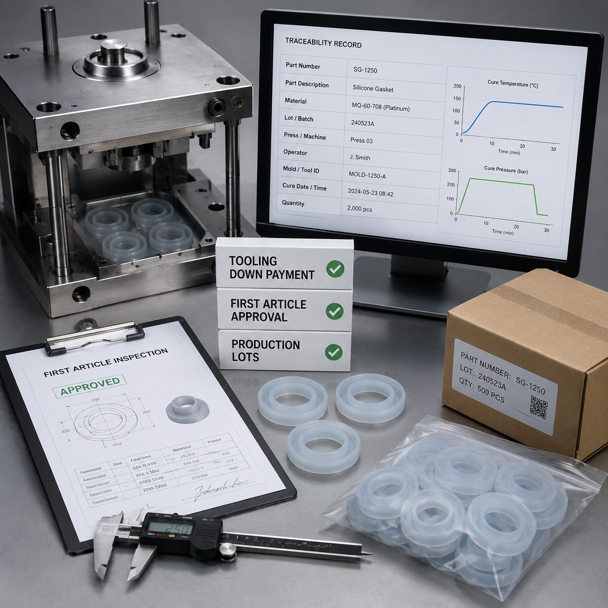
Payment & Post-Sales Support
Payment arrangement on a custom silicone molding order is customarily staged—a tooling down payment, a balance against first-article approval, then production billed in lots. Requesting a silicone molding manufacturer to frame the quote in this manner protects you, as you physically approve the sample prior to expenditure on production. A supplier who rejects any staging on a compression moulding job deserves further review.
Post-sales support is facilitated via the same traceability network. If an issue arises on a shipped lot, batch records tie the part back to its press, operator, and material—so a failure is identified, not assumed. That’s why you want your compression molding business with a mold-builder, an operator, and a material-puller.
06 /
ENGINEERING RESOURCES
Interactive Engineering Tools & Calculators
Process & Cost Selector
Silicone Material Selector
ISO 3302-1 Tolerance Calculator
07 /
KNOWLEDGE BASE
Frequently Asked Questions
Detailed engineering answers regarding silicone compression molding economics, capabilities, and material compliance.
Yes—a solid HCR/HTV silicone is a common compression molding grade. The process is suited to gaskets, seals, grommets, keypads, and higher cross-section parts at low-to-medium volumes. Excessively high-volume programs, or ultrathin walls, sound the death knell for HCR in favor of LSR injection.
This is a function of volume. Up to about 5,000 pieces, compression molding tends to be a more economical choice since the tooling expense is trivial compared to the cost of an injection mold. Beyond that point, injection molding’s 10-60 second cycle length makes it justifiable despite the higher tooling. High-temperature HCR silicone and thick sections do the same in favor of compression molding at most volumes.
Industry parameters cite simple compression molds in the $5,000-$20,000 range, complex multi-cavity tools in the $1,000-$5,000 range. Your figure is controlled by cavity count, part size and complexity. Engelhardt quotes tooling, de-flashing, and inspection as distinct cost lines so the overall is transparent before commitment.
Dimensional tolerance – ISO 3302-1, 1-2: 10-16mm fixed dimension – 0.15-0.20 mm; or similar. Engelhardt – Class M1-M2 for precision features such as ribs and bosses. For instance 0.15-0.20 mm on 10-16 mm fixed dimension. Solid silicone durometer 20-80 Shore A, no more than 5 Shore A hardness variation. We can check your drawing and advise on a feasible class before the tooling quote is settled.
Flash is a natural byproduct of compression molding, and must be thoughtfully managed. We weigh each silicone slug to cavity, to enable advanced fill control, each parts’ parting line is trimmed on automatic, frozen/cryogenic, or manual trimming lines, then a first-article test and MES-controlled cure profile later the run is uniform.
Engelhardt molds other food-grade HCR silicone without difficulties, and operates an ISO 9001 and IATF 16949 quality management system. Material compliance declarations such RoHS and REACH are available on request. For a food or medical product send us the specification, and we confirm compound and documentation before quote.
Typically tool- 2-8 weeks, depending on complexity-, and first-articles of the part in 7-12 days. Production leadtime is project specific, defined per run by volume. Although compression molding is preferred for lower-to-medium runs, the OEM use order- to avoid a too-high MOQ.
– provided the flash and cure profile are controlled and verified. Engineers’ top concern is that poorly cured and molded parts can create bacterial pockets, so de-flashing for medical and food-contact products must be validated not assumed. Engelhardt uses a MES/QMS for lot traceability, and celebrates first articles on all production runs.