Get in Touch with Engelhardt

Plastic injection molding will transform a thermoplastic resin pellet into a precision molded part at volumes of a few thousand to hundreds of millions per year. If this is your first time purchasing molded components – or the application requires a plastic part capable of surviving heat and UV soak in an automotive under-hood environment, receiving a sterilization cycle in a hospital, or being nested into a snap-fit assembly 50 times per minute on an injection molding production line – the decisions you make before the first part hits the first machine will determine 80% of your part cost and close to 100% of your part quality. This article takes you through the process, the materials and tolerances, the cost drivers, the typical defects, and the seven questions to ask any injection molder before your first purchase order.
💡 Quick Specs: Plastic Injection Molding at a Glance
- Cycle time: 15–90 seconds per shot (geometry-dependent)
- Standard tolerance: ±0.127 mm (±0.005 in) per ISO 20457:2018
- Precision tolerance: ±0.025 mm (±0.001 in) achievable with controlled tooling
- Clamping force range: 50 to 2,000+ tons
- Shot-to-shot weight variance: below 0.5% on servo-hydraulic presses
- Typical resins: ABS, PP, PC, PA (Nylon), POM, TPE, PBT, PC/ABS
- Economic break-even vs CNC: roughly 3,000–5,000 parts for simple geometries
- Global market: USD 298.7 billion (2024), projected USD 312.7 billion (2025)
What Is Plastic Injection Molding and Why Does Nearly Every Industry Use It?
Plastic injection moulding involves injecting a heated, flowing thermoplastic resin into a machined steel or aluminum mold cavity at high pressure, allowing it to cool, and then ejecting it as a formation of the finished plastic component. In contrast with CNC machining (which uses subtraction) or 3-D printing (additive, with material grown one layer at a time), each injection moulded component is formed on a repeating cycle in a single operation— transforming polymer pellets into a component that can be removed and replaced, over and over again on the order of every 15 to 90 seconds—without human intervention. It is this repeatability that has made injection moulding the dominant process for manufacturing plastic components today in the automotive, medical device, electronic, and packaging industries.
The global injection molding market was valued at USD 298.7 billion in 2024 and is expected to reach USD 312.7 billion in 2025, according to Grand View Research. The scale is not accidental: once a mold is built, the cost per molded part falls to cents, while CNC or 3D-printed equivalents stay at dollars per unit. The math is why injection molding locks into the product development decision at surprisingly low volumes.
When Does Injection Molding Beat CNC or 3D Printing Economically?
Break-even is highly dependent on part complexity and tolerance requirements, but a reasonable rule of thumb is that injection molding becomes less expensive than CNC machining somewhere between 3,000 and 5,000 units for simple geometries, and between 500 and 2,000 parts for features that are difficult to machine (undercuts, living hinges, walls below 2 mm). Against SLA or SLS 3D printing, injection molding usually wins above a few hundred units because the mold cost amortizes quickly once material and print time dominate. Above roughly 5,000 parts, injection molding is almost always the correct economic answer for thermoplastic components.
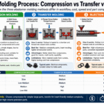
This is exactly why moldings is the dominant manufacturing process in consumer products, medical devices, and automotive sub-assemblies. For a quick side-by-side of various molding processes, please see our molding process comparison matrix.
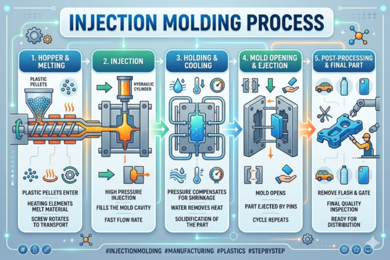
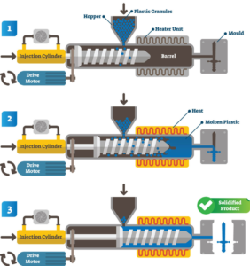
How the Injection Molding Process Works: Four Stages That Define Cycle Time
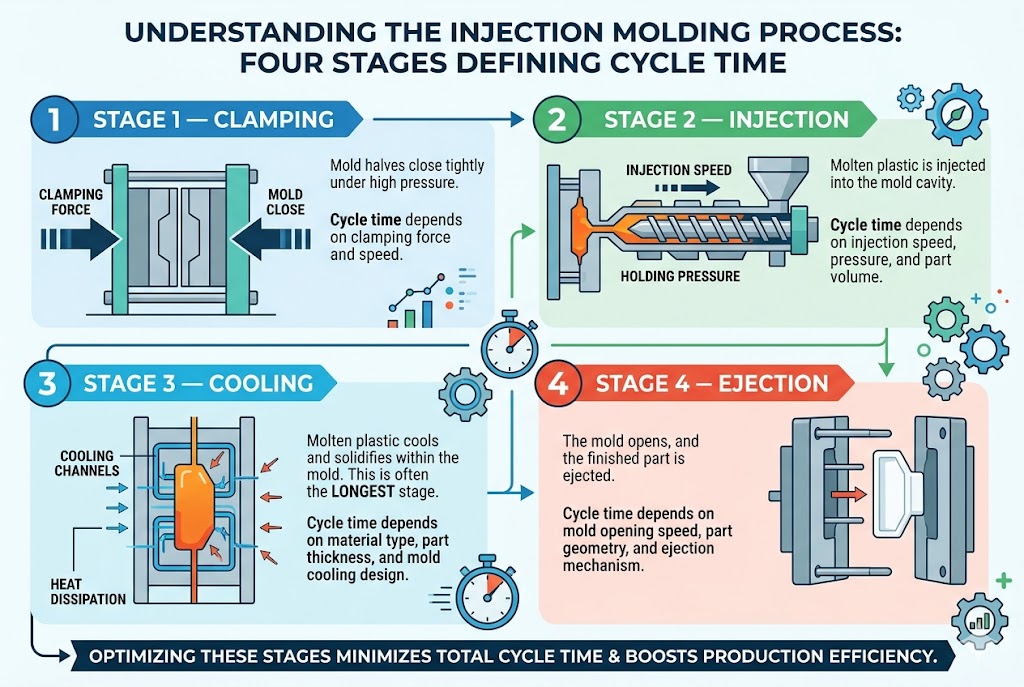
Every injection molding operation – whether on a 50-ton benchtop press or a 2,000-ton automotive tool – progresses through four fundamental stages. You can familiarize yourself with these stages in order to quickly test a molder’s response when you ask “how fast can you make this part?” or “why is the quote so high?” – because cycle time, clamping force, and cooling dynamics each map directly to a stage.
Stage 1 – Clamping. When the two halves of the mold meet, they do so under significant hydraulic or electro-hydraulic pressure. Clamping force must be able to withstand the projected area of the part times the injection pressure or else the mold will open during the shot and flash will escape along the parting line. Larger parts require larger tonnages – and a 300 by 200 mm automitive trim panel can use anywhere from 400 to 600 tons.
Stage 2 – Injection. The resin pellets are injected into the heated barrel where a reciprocating screw melts the resin and guides the molten plastic through a nozzle and runner system into the mold cavity. Injection pressure is commonly 60-180 MPa (9,000-26,000 psi) – dependent on resin and part wall thickness. The screw precisely meters out the material for each shot making sure that the shot weight is consistent from cycle to cycle – with modern servo-hydraulic presses that level of precision is often less than 0.5%.
Stage 3 — Cooling. This is the dominant phase. According to process engineering data published by RJG Inc., cooling can account for up to 85% of total cycle time. Coolant circulating through channels inside the mold pulls heat out of the solidifying part at a rate determined by wall thickness, resin thermal conductivity, and channel geometry. This is why wall thickness is the most influential design decision for cycle time: cooling time scales with the square of thickness, so a 3 mm wall cools roughly four times slower than a 1.5 mm wall. BASF publishes a technical paper on estimating cooling times in injection molding that documents the exact mathematical relationship.
Stage 4 – Ejection. As soon as the solidified plastic reaches ejection temperature (a process property), the two halves open, the ejection pins eject finished parts, which drop into collection in bins or onto conveyors. The cycle immediately begins again. Modern machines and molds that are properly designed produce high-quality parts unattended for hours at a time – driving the cost down such that plants run 24/7.
Engineering Note. Because of the dominance of coolling, wall thickness becomes the invisible “hidden” cost driver in injection molding. Transferring a wall from 2 mm thick to 4 mm thick increases the cycle time from 18 seconds to 60+ seconds – making a $0.12 part into a $0.40 part on the same machine. If wall thickness isn’t brought into the DFM discussion, then the DFM was incomplete.
For a look at how these four stages run in practice at scale, see our 400-machine plastic injection molding capability.
Injection Molding Materials: Eight Common Resins and How to Pick One
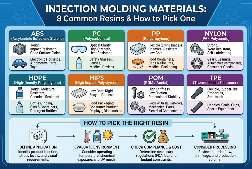
Of the hundreds of thermoplastic resins available for injection molding, only around eight support the vast majority of real world production. The second most important design decision you will take – after wall thickness – is selection of the plastic resin because it determines the storage requirements of the tooling steel, the amount of growth compensation, the optimum drying conditions, and even (in medical or food contact markets) your regulatory pathway.
| Resin | Key Properties | Shrinkage | Typical Applications |
|---|---|---|---|
| ABS | Impact-resistant, good surface finish, paintable | 0.4–0.7% | Consumer electronics housings, automotive interior trim |
| PC | Optical clarity, high heat resistance, tough | 0.5–0.7% | LED lenses, safety equipment, medical device covers |
| Nylon (PA6/66) | Wear-resistant, strong, absorbs moisture | 0.8–1.5% | Gears, bearings, structural brackets, cable ties |
| PP (polypropylene) | Chemical-resistant, lightweight, living hinge capable | 1.0–2.5% | Packaging, household containers, automotive bumpers |
| POM (acetal) | Low friction, high stiffness, dimensionally stable | 1.8–2.5% | Gears, clips, valve bodies, conveyor components |
| TPE/TPU | Rubber-like flexibility, good for overmolding | 0.5–2.0% | Grips, seals, soft-touch surfaces, wearables |
| PC/ABS | Combines PC toughness with ABS processability | 0.5–0.7% | Laptop housings, power tool casings, instrument panels |
| PBT | Electrical insulation, chemical resistance | 1.5–2.0% | Connectors, switch housings, sensor enclosures |
Which Plastic Is Best for Injection Molding?
The honest answer is that the best plastic resin is the one whose mechanical properties, chemical resistance, thermal range, and regulatory profile match your part’s service environment – not the cheapest one. A medical housing that will be gamma sterilized should not be made from polypropylene (PP) even though PP is the second-most common thermoplastic by volume; gamma radiation chain-scissions PP and destroys its impact strength. On the other hand, specifying polycarbonate for a sterilized disposable syringe plunger will add unnecessary cost because of P’s higher processing temperature. The decision matrix should start with service environment (temperature, chemical exposure, UV, load), add regulatory constraints (FDA, NSF 61, USP Class VI, UL 94 V-0, IATF 16949), and then consider cost per kg. Only then can a good molder quote an appropriate build.
Engineering Note: Glass-fiber reinforced grades (GF10, GF20, GF30) support and strengthen the part yet significantly abrade softer mold cavity inserts. Glass-reinforced resins require hardened tool steel-h13 or S136 – for any cavity surface coming into contact with melt flow. Purchasers may note this too late when their prototype P20 mold fails at 20000 shots instead of the anticipated 100,000.
Types of Injection Molding: Standard, Insert, Overmolding, Gas-Assisted, and More
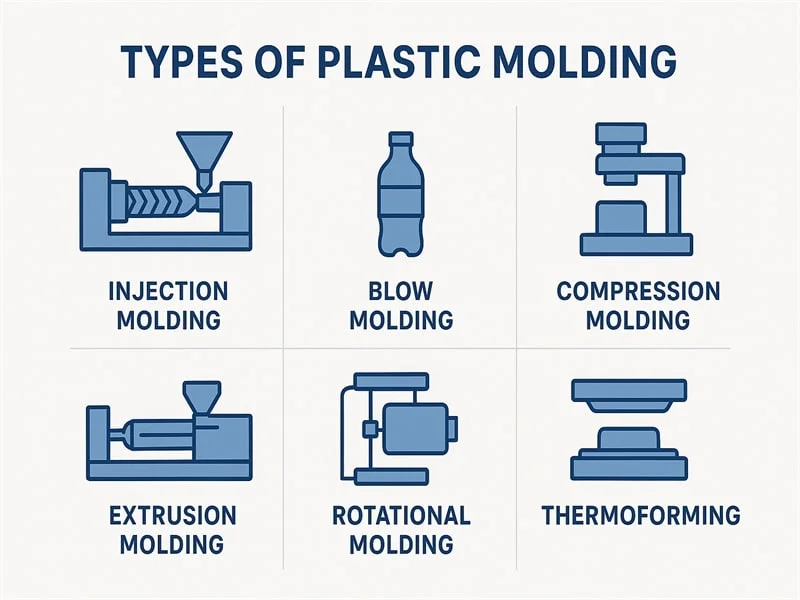
Most parts are produced from standard single shot injection molding. There are, however, a small number of process variations for geometries or functions that standard molding can’t provide effectively, and knowing which variation solves which problem will prevent paying for complexity you do not require. The common modern injection molding techniques are:
- Insert molding — a pre-formed metal insert (threaded bushing, electrical contact, fastener) is loaded into the mold before injection, and the plastic encapsulates it in one cycle. Eliminates secondary assembly. Common in electrical connectors and metal-to-plastic insert bonding applications.
- Overmolding – the injection machine produces a second shot (usually soft, TPE) in the injection mold after the first shot (usually hard, ABS or PC). Creates a single component with two characteristics. Common for soft coverings, damping, and soft grips.
- Two shot (dual-injection) molding – the injection machine produces two different materials by sequential injection via a moving mold in one shot. Produces a bi-material part without secondary adhesive bonding. Common in automotive switches and electronics.
- Gas assisted injection molding – nitrogen is injected into the process after the initial shot to hollow out thick sections (increases efficiency) and reduce fire-warpage.
- Structural foam molding – a foamed core (chemical blowing agent) is created inside a solid skin in order to reduce the part weight and clamping forces during processing.
- Mole injection molding- produces sub-gram components at micrometer tolerances, used in med-devices and electronics.
A common error is that two shot molding and overmolding are the same. They are not. Two shot molding requires a special orbiting mold, and a dual barrel injection machine. This increases tooling cost 40-60%. Overmolding is two cycles on the same machine, with a transfer between. If you want a soft grip on a rigid body, moderate volumes overmolding will be cheaper in the end. If you are running millions of identical parts, and cycle time is king, two shot over time drops in per part economics. Another type of process to consider in a project with elastomers is rubber injection molding, which also is parallel operation but with different chemistry.
“Gas-assisted injection molding pays off above roughly 3 mm wall thickness. Below that, you are buying mold and machine complexity without a meaningful reduction in sink or cycle time”.
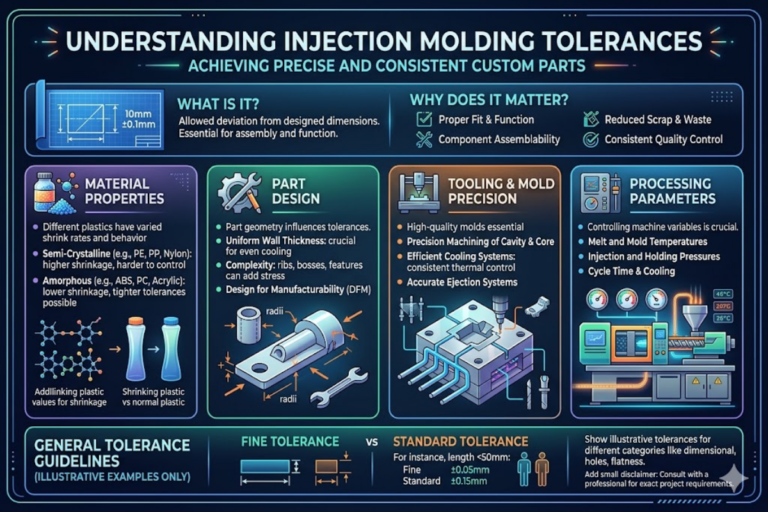
Tolerances and Quality Control: How Tight Is Tight Enough?
Injection molding plastic tolerance is the least understood metric in the entire process and the reason for most cost overruns. Most procurement professionals always buy “tolerances every where”, confusing tight specs with quality. In reality, tightening unnecessary tolerances multiplies mold cost with no functional improvement.
The international standard for tolerancing injection molded plastic parts is ISO 20457:2018 “Plastics moulded parts — Tolerances and acceptance conditions”, which establishes general tolerance classes and acceptance criteria for dimensional, geometric, and visual features of plastic molded parts. The German national standard DIN 16742:2013 predates and informs ISO 20457 and uses a tolerance group (TG) system (TG 1 through TG 7) from finest to coarsest tolerance. Most thermoplastic production falls into TG 4 to TG 6, which maps closely to ±0.127 mm (±0.005 in) general tolerance on typical feature sizes.
What Tolerances Can Plastic Injection Molding Achieve?
Standard injection molding production holds ±0.127 mm (±0.005 in) on most dimensions without special effort. With precision-grade tooling, tightly controlled resin shrinkage, and servo-driven process parameters, ±0.025 mm (±0.001 in) is achievable on critical features — a level many first-time buyers assume requires CNC machining. The tradeoff is cost: tighter tolerances drive mold steel from P20 to H13 or S136, add polishing and fitting labor, slow the process window, and extend cycle time. Before specifying ±0.025 mm on any feature, ask yourself: does this feature actually mate with another component, and if so, does the mating component hold an equivalent tolerance? If the answer is no, the tighter tolerance is wasted money.
Material shrinkage is the latent variable . For the available materials (0.4% for ABS, up to 2.5% for POM and PP), it cascades diectly into cavity shape – a cavity must be machined larger than the expected final part by just the right amount which depends on both mold temperature and hold pressure. Quality assurance for critical precision injection molds is then a mixture of coordinate measuring machines (CMM) for 3D verification, optical projection for 2D profile verification, and incoming material rheology testing to catch resin batch discrepancies early on in the process path. You can quantify expected manufacturing tolerances for your resin material with our injection molding tolerance calculator.
Plastic Injection Molding Cost: The 80/20 Rule Buyers Need to Know
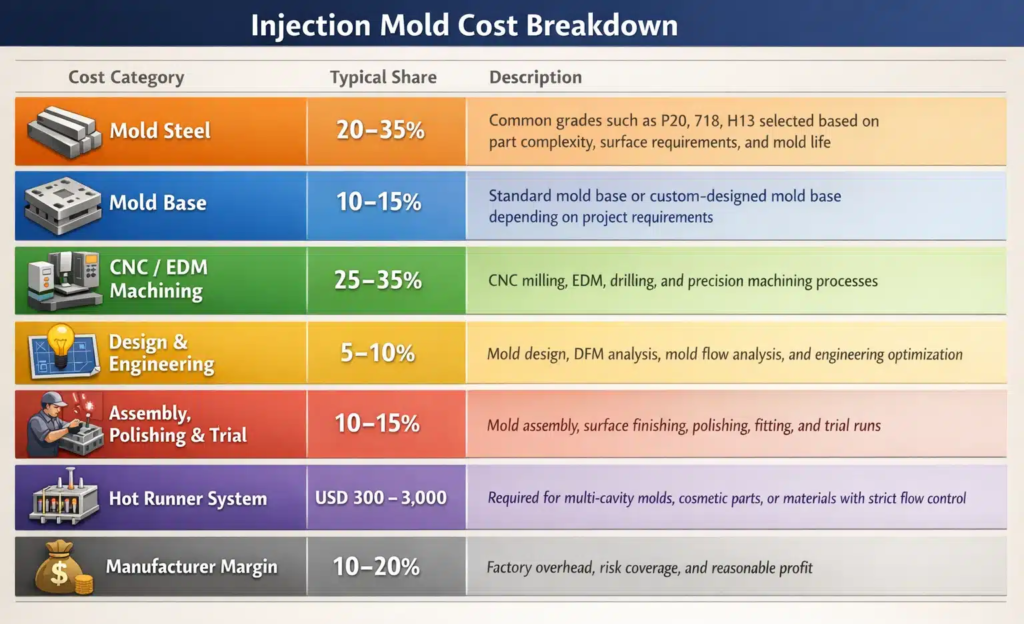
Roughly 80% of your part cost is determined by three design decisions before 1 pellet has entered the hopper – resin selection, wall thickness, and mold cavity count. Design engineer and customer negotiation focus then revolves around the remaining 20% – once the tool is in production, secondary operation and logistics decisions will ultimately determine pricing. The same part from the same vendor can quote at anywhere from $0.40 to $0.12 depending only on that week and that vendor.
Total cost breaks into three buckets:
1. Tooling Cost. Prototype simple aluminum single-cavities runs in the thousands; multi-cavity production molds, HRC steel with hot runner, can easily cost USD50k or more, even USD 100k for automotive parts. Cost drivers: cavity number, part complexity (undercuts, lifters, side actions), tool steel grade (P20 for prototype, S136 or H13 for production), surface glossiness (SPI A-1 mirror polish is expensive), hot versus cold runner system.
2. Per-capita manufacturing cost. This the sum of raw material cost ($/kg part mass, plus runner and sprue remelt losses), machine hour rate (MHR), divided by total output part number per hour, and direct labor. A thin-walled polypropylene container with 12-s cycle time may only cost $0.05 per part in raw material and machine time; a thick-walled polycarbonate enclosure at 60-s cycle from the same shot is closer to $0.40.
3. Secondary operation. Pad printing, ultrasonic welding, assembly, inspection, and packaging each add to the per-part cost. Vertically integrated factories find this less expensive than internationalized supply chains, provided once/a cycle line rates can be maintained.
| What Drives Cost Up ⚠️ | What Drives Cost Down ✔ |
|---|---|
| Tighter tolerances on non-critical features | Uniform wall thickness (faster cooling) |
| Undercuts and side actions | Commodity resins (PP, ABS) vs engineering grades |
| Mirror or textured surface finish | Higher volume amortizing the mold cost |
| Engineering resins (PEEK, PEI, LCP) | Family molds (multiple parts per tool) |
| Low annual order quantity | Design simplification and feature consolidation |
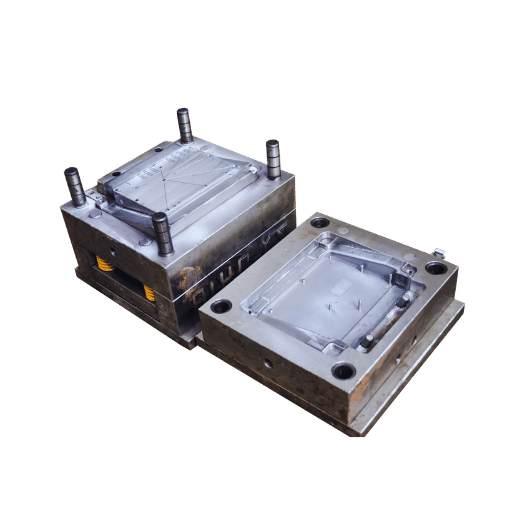
How Much Does a Plastic Injection Mold Cost?
Tooling averages several to tens of thousands of dollars for a basic prototype aluminum single-cavitate mold, to over USD 50 – 100K for multi-shared eye catching production tooling with hot runner system, complex ejector formers and other frills. Cost decision criteria are part geometry (cavity number, undercuts, slides, lifters), tool steel (P20 for prototypes, H13/S136 for production), runner (any of hot vs cold), and surface finishing preferences. Buyers underestimate lead time impact more than cost two times or more, a “4 weeks” tool ultimately shoots to 8-12 weeks production run when DFM iterations are repeated. Using our injection molding cost estimator you can estimate the tooling investment and unit per part cost.
Defects and the DFM Checklist: Where Injection Molded Parts Actually Fail

The unfortunate reality is that the vast majority of injection molding defects come down to mold design not machine parameters. When Fictiv published a product study on gate sizes and placement, they identified gate-related decisions as the root cause of most short-shot, weld-line, and cosmetic defects. The takeaway for buyers: no amount of process tuning will cure a poorly designed mold, and no amount of injection pressure will fix a gate placed incorrectly in the mold.
The six most common defects on molded parts and the culprits:
| Defect | Dominant Root Cause | DFM or Process Fix |
|---|---|---|
| Sink marks | Thick wall sections, uneven cooling | DFM — core out thick ribs to uniform wall |
| Warpage | Non-uniform wall thickness, unbalanced cooling | DFM — uniform wall; conformal cooling |
| Short shots | Gate too small, low injection pressure, poor venting | DFM — resize gate; add vent channels |
| Flash | Insufficient clamping force, worn parting line | Process — increase clamp; mold maintenance |
| Weld lines | Melt fronts meeting at low temperature | DFM — relocate gate; raise melt temp |
| Voids / bubbles | Trapped gas, wet resin, low pack pressure | Process — dry resin; add packing time |
Notice the trend: four of these six defects have a DFM solution in place rather than a process correction. The white-elephant DFM error so often seen on engineering forums like r/MechanicalEngineering is to request tighter tolerances on all dimensions instead of only the critical measures. In one shop-floor account, that one error doubled mold cost with no functional improvements. The second most populous human error is neglecting a moldflow simulation on complex geometries. A $2,000 simulation that would have called out the warping problem becomes a $15,000 mold rework.
In our recent Meitu Engelhardt project, a Tier-2 automotive supplier had issues controlling warpage on a PA66-GF30 HVAC duct assembly as two previous molders placed gates at the centroid. A flow simulation revealed that sequential valve gates in eight strategic locations, teamed with conformal cooling inserts in the snap-fit zones, kept warpage to less than 0.3 mm on a 48-second cycle. The part has not produced a single OEM assembly rejection since transfer. The moral: gate location is not a process variable; it is a mold design fiat, and the investment in simulation is worth the delay to cut steel.
How to Evaluate a Plastic Injection Molding Manufacturer Before the First PO
The seven questions below make a supplier evaluation matrix that will differentiate a good through put-oriented custom plastic injection molder from a contract job shop. Each question targets a specific failure seen in real buyer-side procurement reviews.
- Certs held: ISO 9001:2015 at minimum, IATF 16949 for automotive, ISO 13485 for medical. Request the cert number and crosscheck with the registrar.
- Mold steel info: will they enter the steel grade (P20, H13, S136, NAK80) explicitly in writing on the tooling quote? Less expensive quotes often are based on lower-quality steel that will crack after 20,000 shots.
- MES / ERP data tracking: do they have digital production logs from raw material batch to shipped carton? Manual paper-trail shops have a hard time tracing back through an incident to find the root cause.
- In-house tooling: do they cut their own molds in-house or subcontract? In-house tooling means quicker DFM and quicker revisions.
- Secondary operations: pad printing, ultrasonic welding, assembly, and inspection under one roof reduce per-part costs and the need to move parts between stations.
- DFM capability: will they run Moldflow on your part before the steel is cut? A molder who refuses is a molder sending you rework costs.
- Portfolio of applications: get three use case examples from your specific industry with named (or anonymized but industry-specific) results – dimensional tolerance, cycle time, reject rate.
For a detailed walk-through of how these parameters translate into a production setting, refer to our plastic injection molding services.
Frequently Asked Questions About Plastic Injection Molding
What is plastic injection molding and how does it work?
View Answer
Plastic injection molding involves forcing heated thermoplastics through a heated barrel and into a precision-machined mold cavity, where the resin cools and hardens into the finished part and is then ejected. The process involves four stages—clamping, injection, cooling, and ejection—that occurs in cycles lasting 15 to 90 seconds. Due to the high precision of the mold, the dimensional tolerance remains very low even for billions of units—thus making manufacturing of automotive, medical, and consumer devices very cost-effective.
How much does a plastic injection mold cost?
View Answer
Typical cost for a basic prototype aluminum single-cavity mold is in the low thousands of dollars, whereas multi-cavity, hardened steel molds with hot runners, side actions, and unusual part geometries can reach the hundreds of thousands. This is primarily affected by the complexity of the mold, number of cavities, and surface textures specified. Lead times for steel tooling are generally 2-3 weeks for prototype tooling and 6-12 weeks for production tools.
What types of plastic can be injection molded?
View Answer
Most thermoplastics mold well — ABS, PC, PP, PA, POM, PBT, PC/ABS, and TPE cover most real-world production. Engineering grades such as PEEK and PEI are also processable.
What is the minimum order quantity for custom injection molding?
View Answer
MOQ starts at roughly 100 pieces for prototype runs on aluminum or soft-steel tooling. Standard production orders typically begin at 1,000 units to spread fixed mold cost across enough pieces for favorable per-part pricing. Below those thresholds the tooling amortization disproportionately dominates per-unit cost, and CNC machining or urethane casting usually remain more economical until you cross the break-even volume.
What is the difference between insert molding and overmolding?
View Answer
Insert molding involves positioning a pre-fabricated insert (often a contact or a bushing) into the mold prior to injection of the plastic while overmolding refers to the application of a second layer of molten plastic (usually soft TPE over a hard ABS or PC). Both processes save labor costs over secondary assembly, but typically address different functional requirements.
How long does it take from design to first production?
View Answer
The typical lead time for injection molding process is: design review and draft analysis 1-3 days; tool manufacture and testing 3-8 weeks (depending on size and complexity of the tooling); first-article samples 1 week from the completion of tooling; approval of samples, tooling modifications 1-2 weeks; production start-up 4-8 weeks (depending on order size and part complexity. Maximum of 1 week of production load before shipping the first batch. Total lead time from approval to first shipment is typically 5 to 10 weeks).
Ready to run your custom plastic injection molding project?
Send us your CAD file and we will return DFM feedback, tooling options, and a full quote within 24 hours.
Data in this guide is compiled from ISO and DIN tolerance standards, Grand View Research market data, BASF technical literature, RJG process engineering publications, and production-floor experience from the Meitu Engelhardt engineering team operating 400+ injection molding machines. Specific shrinkage rates, cycle times, and tolerances will vary with your resin batch, mold condition, and part geometry — treat the numbers above as engineering ranges, and request first-article data for your specific application.
References & Sources
- ISO 20457:2018 — Plastics moulded parts — Tolerances and acceptance conditions — International Organization for Standardization
- Injection Molding Market Size and Share Report, 2024–2033 — Grand View Research
- Estimating Cooling Times in Injection Molding (Technical Information) — BASF SE
- How to Determine Injection Molding Cooling Time — RJG Inc.
- Product Study: Gate Sizes and Placement in Injection Molding — Fictiv Engineering
- DIN 16742:2013 — Plastic moulded parts tolerances — Deutsches Institut für Normung (German national standard)
Related Articles
- Custom plastic injection molding services — full capability overview
- Injection molding cost estimator for tooling and per-part pricing
- Injection molding tolerance calculator by resin and mold type
- Custom rubber molding services and elastomer capabilities
- Silicone vs rubber: key differences for engineers and procurement teams