Get in Touch with Engelhardt

Liquid silicone rubber (LSR) molding has become the fastest-growing segment in silicone processing, driven by demand from medical device manufacturers and automotive OEMs who need tight tolerances and biocompatible materials at production scale. Globally, the liquid silicone rubber market reached $1.36 billion in 2023 and is projected to hit $2.41 billion by 2030 — growth fueled by the shift from compression-molded high-consistency rubber to automated liquid silicone rubber injection molding processes. This guide breaks down the process science, DFM rules, material selection criteria, and honest cost data that engineers and procurement teams need before specifying LSR for a new project. For manufacturers evaluating silicone part production, understanding the distinctions between LSR and alternative processes is the first step toward controlling per-part cost and lead time. Engelhardt provides custom rubber molding services across all three major rubber processing methods.
Quick Specs — Liquid Silicone Rubber (LSR)
Material Type: Two-part platinum-cured thermoset silicone elastomer
Hardness Range: 5–80 Shore A
Operating Temperature: −50 °C to +250 °C (specialty: −110 °C to +300 °C)
Injection Pressure: 500–5,000 psi
Typical Cycle Time: 10–60 s (part-dependent)
Standard Tolerance: ±0.1–0.2 mm (precision: ±0.02 mm)
Shrinkage: 2–3 % typical, up to 5 %
Key Certifications: FDA 21 CFR 177.2600, USP Class VI, ISO 10993
What Is Liquid Silicone Rubber — And Why Does the “Liquid” Part Matter?
Liquid silicone rubber (LSR) is a two-part, platinum-catalyzed thermoset polymer built on a siloxane backbone — alternating silicon and oxygen atoms (Si-O-Si) with organic methyl or vinyl side groups. Unlike peroxide-cured rubbers that generate byproducts requiring post-bake removal, LSR uses addition-cure (hydrosilylation) chemistry: a platinum catalyst triggers a reaction between vinyl groups on the A-component and Si-H groups on the B-component, producing zero byproducts. This clean cure is why LSR passes the stringent extractables and leachables testing required for FDA 21 CFR 177.2600 food contact and USP Class VI biocompatibility without additional processing steps.
What matters most is the word “liquid.” Before curing, LSR has a viscosity comparable to peanut butter — low enough to be pumped, metered, and injected through automated equipment but viscous enough to stay in the mold cavity. This self-leveling flow behavior means LSR fills complex geometries — thin walls, micro-features, undercuts — that would trap air or leave knit lines in higher-viscosity rubber compounds. With proper tooling, LSR injection achieves near-zero flash because the low-viscosity material does not force its way past precision parting lines the way gum-stock HCR does.
In terms of performance, the mechanical property range spans 5–80 Shore A hardness, continuous service from −50 °C to +250 °C, and elongation at break ranging from 200 % and 1,100 % depending on grade. These numbers matter because they define the design envelope: an engineer can specify a single material family that covers everything from ultra-soft infant care products (10–20 Shore A) to semi-rigid automotive connector seals (60–70 Shore A).
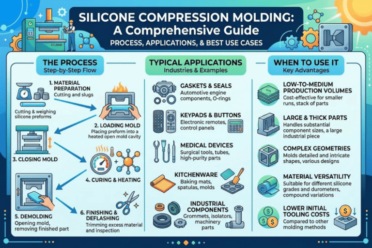
LSR vs. HCR vs. RTV — a quick orientation: High-consistency rubber (HCR) arrives as solid gum stock, requires manual loading into open molds, and cures via compression or transfer molding over 3–10 minutes per cycle. Room-temperature vulcanizing silicone (RTV) cures without heat, typically via condensation chemistry, and is used for potting, casting, and prototyping rather than production molding. LSR occupies the middle ground — it requires heat to cure (150–200 °C) but arrives as a pumpable liquid that enables fully automated injection molding with cycle times of 10–60 seconds.
Why does automated metering matter? The A and B components must be mixed at a precise 1:1 ratio. Manual mixing introduces variability that shows up as inconsistent cure, soft spots, or reduced tear strength. Automated static mixers eliminate that variable entirely — the equipment meters, mixes, and injects with repeatability that manual processes cannot match.
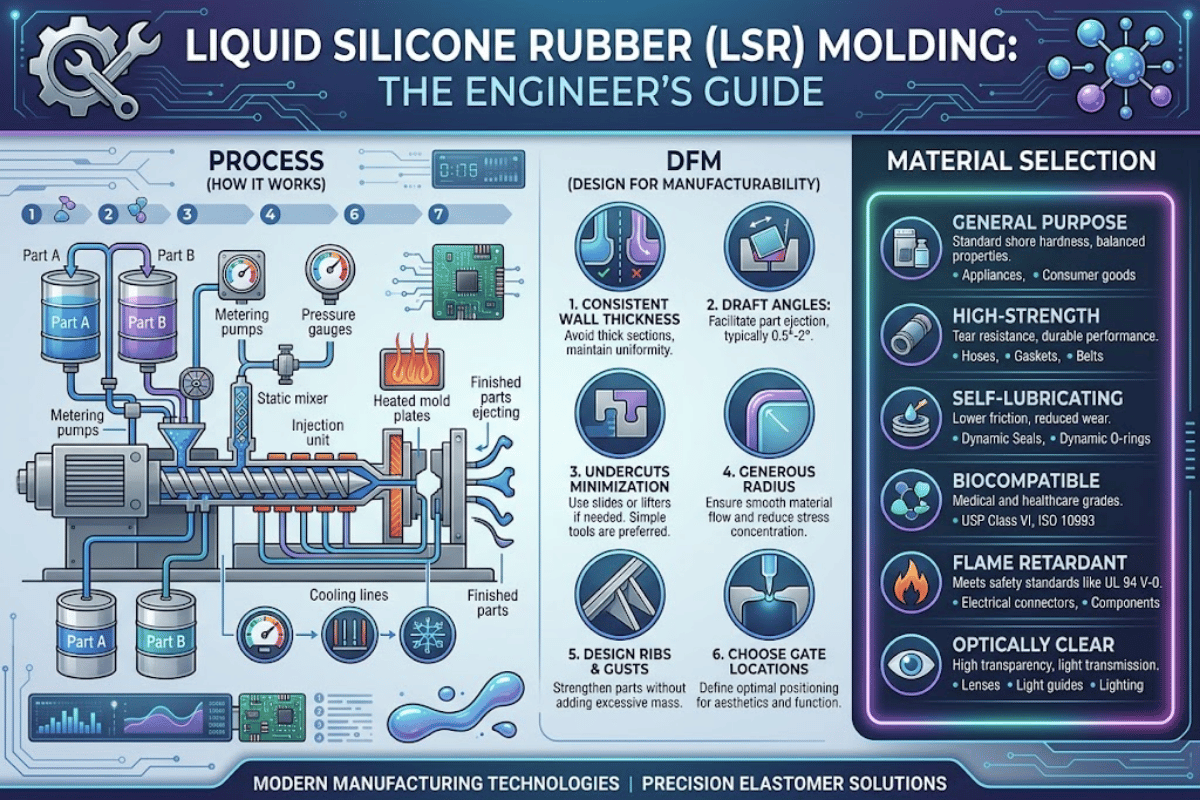
How the LSR Injection Molding Process Works — Step by Step
How Does Liquid Silicone Rubber Molding Work?
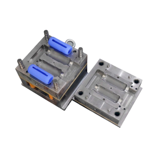
Liquid silicone rubber molding is an injection process where two liquid components (Part A containing the platinum catalyst and Part B containing the crosslinker) are pumped at a 1:1 ratio into a static mixer, then injected into a heated steel mold at 150–200 °C. Heat triggers rapid vulcanization — typically 10–60 seconds — after which the cured elastomeric part is demolded. Unlike thermoplastic injection molding where the mold is cooled, LSR molds are heated because LSR is a thermoset that requires elevated temperature to crosslink. This reversed thermal profile is the single most important distinction engineers must understand when transitioning from plastic to silicone part design.
Overall, the process breaks down into six stages that field engineers and tooling designers should understand in detail:
Step 1 — Metering and Mixing. Pneumatic or servo-driven pumps draw Part A and Part B from separate drums (typically 20 L pails or 200 L drums) through a pigment additive injector (if color is required) and into a static mixer. The static mixer contains helical elements that fold the two streams together over 12–24 elements, producing a homogeneous mix without moving parts. Ratio accuracy of ±1 % is standard; ±0.5 % is achievable with servo-driven systems.
Step 2 — Injection. The mixed LSR is fed into the barrel of a purpose-built injection unit. The barrel and screw are water-cooled to prevent premature cure (scorching). Injection pressure ranges from 500 to 5,000 psi depending on part geometry, wall thickness, and gate configuration. Shot sizes for LSR machines typically range from 5 cc to 5,000 cc.
Step 3 — Mold Filling. LSR enters the heated mold (150–200 °C) through a cold-runner system. The cold runner keeps the LSR in liquid state until it passes through the gate into the hot cavity. This is the reverse of thermoplastic molding, where hot runners keep plastic molten and the mold is cooled. Cold-runner valve gates are preferred because they eliminate runner waste and provide clean gate vestige.
Step 4 — Vulcanization (Cure). Once the cavity fills, heat from the mold triggers the platinum-catalyzed addition reaction. Cure time depends on wall thickness, mold temperature, and LSR grade — thin-wall parts (0.5–1.0 mm) may cure in 10–15 seconds at 180 °C, while thick-wall parts (5+ mm) may require 45–60 seconds. Once complete, the crosslinking reaction is irreversible — once cured, LSR cannot be remelted or reprocessed.
Step 5 — Demolding. The mold opens and parts are removed by ejector pins, air blast, or robotic pick-and-place. LSR’s natural release properties (low surface energy) and flexibility allow parts with moderate undercuts to be stripped from the mold without damage — a significant advantage over rigid thermosets.
Step 6 — Post-Cure (Optional). Some applications — particularly medical devices and food-contact parts — require a post-cure step of 2–4 hours at 200 °C in a convection oven. Post-cure drives off residual volatile compounds and completes any remaining crosslinking, improving compression set and meeting extractables specifications.
📐 Engineering Note: Clamp force calculation for LSR: Clamp Force (tons) = Projected Area (in²) × Cavity Pressure (psi) ÷ 2,000. For a 4 in² projected area at 3,000 psi cavity pressure, minimum clamp force = 6 tons. Always add a 10–15 % safety margin. Injection pressure typically ranges from 500 to 5,000 psi — lower than most thermoplastics due to LSR’s low viscosity.
“Moldmakers can machine vents to 0.00001 in. and generally hold vent depths to around 0.000020 in. – at those tolerances, proper venting becomes the difference between a flashless part and a scrap bin.”
— Troy Smith, Global Sales Director, Roembke Mfg. & Design (32+ years in LSR tooling)
For manufacturers evaluating production-ready LSR capabilities, Engelhardt’s LSR injection molding services cover the full sequence from DFM review through post-cure validation.
LSR vs HCR vs Thermoplastic Elastomers — Choosing the Right Process

Selecting the wrong elastomer process is one of the most expensive mistakes in rubber part development. The decision depends on annual volume, required tolerances, operating temperature, and regulatory requirements. The table below uses specific numbers — not vague “high/medium/low” ratings — so engineers can make direct comparisons.
| Feature | LSR | HCR | TPE |
|---|---|---|---|
| Form | Liquid (two-part) | Solid (gum-like) | Pellets |
| Processing | Injection molding | Compression / transfer | Injection molding |
| Mold Temperature | 150–200 °C (heated) | 150–180 °C (heated) | 20–80 °C (cooled) |
| Cycle Time | 10–60 s | 3–10 min | 15–60 s |
| Tolerance | ±0.1–0.2 mm | ±0.15–0.3 mm | ±0.1–0.2 mm |
| Heat Resistance | −50 to +250 °C | −50 to +200 °C | −40 to +120 °C |
| Biocompatibility | Excellent (FDA / USP) | Excellent | Variable |
| Recyclability | Not recyclable (thermoset) | Not recyclable | Recyclable |
| Volume Sweet Spot | >5,000 units/year | 100–5,000 units/year | >10,000 units/year |
A common error is specifying HCR compression molding when annual volumes exceed 10,000 units — the labor cost of manual loading and longer cycles quickly eclipses LSR tooling investment. Conversely, specifying LSR injection for 500 units per year means the $15,000–$100,000 mold amortizes to $30–$200 per part before material costs, which rarely makes financial sense.
TPE offers the advantage of recyclability and runs on standard thermoplastic injection equipment, but its upper temperature limit of ~120 °C and inconsistent biocompatibility exclude it from medical, food-contact, and under-hood automotive applications where LSR excels.
For engineers who need a side-by-side analysis across all rubber processes — including rubber injection molding, transfer molding, and compression — the molding process comparison matrix provides a decision framework organized by volume, tolerance, and material requirements.
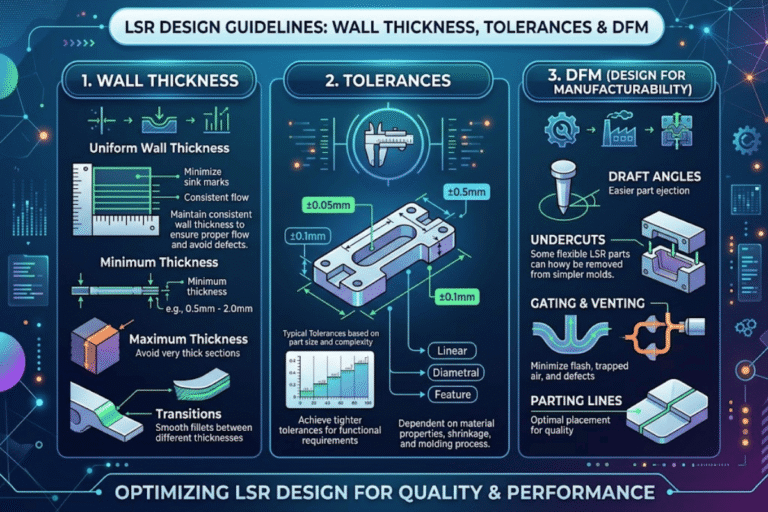
DFM Rules for LSR Molding — Design Decisions That Cut Tooling Costs

What Wall Thickness Should I Design for LSR Parts?
Standard LSR wall thickness ranges from 0.3 mm to 10 mm, with most production parts falling between 1.0 mm and 3.0 mm. Walls as thin as 0.127 mm (0.005 in.) are achievable with specialized tooling and experienced moldmakers, though this pushes tolerances tight enough that not all suppliers can hold them reliably. Thicker walls increase cure time proportionally — doubling wall thickness can more than double cycle time because heat must conduct to the part center for full vulcanization. Wherever possible, core out thick sections and maintain uniform wall thickness to ensure even cure and minimize internal stresses.
The 80/20 rule of LSR tooling: roughly 80 % of per-part cost is locked at the mold design stage. Gate location, runner design, cavity count, and parting line geometry determine cycle time, scrap rate, and secondary operations for the life of the tool. Investing in a thorough DFM review before cutting steel pays for itself within the first production run.
📐 Engineering Note: Wall thickness 0.3–10 mm. Draft angles are not required for LSR (unlike rigid plastics) because the elastomer flexes during demolding — however, 1–2° draft is recommended for automated production to reduce cycle time and improve part-to-part consistency. Gate diameter 0.2–0.5 mm. Shrinkage 2–3 % typical; account for this in cavity dimensions.
LSR DFM Checklist
✔ Wall thickness uniform — or intentionally varied. LSR tolerates thickness variation better than thermoplastics, but uneven sections cause differential cure and warping.
✔ No sharp internal corners — add fillets (minimum 0.5 mm radius) to prevent stress concentrations and tear initiation points.
✔ Undercuts minimized — LSR can flex over moderate undercuts during demolding, but deep undercuts require side actions or collapsible cores that add tooling cost.
✔ Gate location planned — cold-runner valve gate preferred for clean surface finish and zero runner waste. Sub-gate or edge-gate acceptable for non-cosmetic surfaces.
✔ Parting line simplified — complex 3D parting lines increase tool cost and flash risk. Keep the parting line on a single plane when geometry allows.
✔ Draft angles: not required but 1–2° aids automation — speeds robotic demolding and reduces risk of part distortion during ejection.
✔ Material compatibility verified — no sulfur, amines, tin, or other cure inhibitors in contact with uncured LSR (see inhibitor list below).
✔ Post-cure requirements defined — specify temperature, duration, and acceptance criteria in the part drawing if the application requires post-cure.
⚠️ Cure Inhibitor Warning
The following substances inhibit platinum-catalyzed LSR cure and must not contact the material before or during molding:
Sulfur compounds (natural rubber, latex gloves), amines (certain adhesives and epoxies), organotin compounds (PVC stabilizers, condensation-cure RTV silicones), phosphorus compounds, chlorinated solvents, acetone, and MEK. Even trace contamination from handling with latex gloves has caused field failures. Use PTFE-based mold release — never silicone-based mold release, which can transfer cure-inhibiting compounds to the LSR surface.
For parts requiring rubber-to-metal bonding, the metal insert must be primed (typically with a silane-based adhesion promoter) and preheated to mold temperature before LSR injection. Self-adhesive LSR grades can eliminate the primer step for certain substrate combinations.
LSR Material Selection — Durometer, Grade, and Industry Certifications
Material selection for LSR begins with three questions: What certifications does the end-use application require? What durometer (hardness) provides the necessary sealing force or flexibility? And does the part involve overmolding onto another material? The answers narrow the field from hundreds of commercial LSR grades to a manageable shortlist.
Industry Selection Matrix
| Industry | Required Certification | Durometer Range | Typical Applications |
|---|---|---|---|
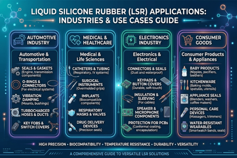
| Medical devices | USP Class VI + ISO 10993 | 20–60 Shore A | Seals, valves, respiratory masks |
| Food & beverage | FDA 21 CFR 177.2600 + LFGB | 40–60 Shore A | Bottle nipples, spatulas, gaskets |
| Automotive | IATF 16949 compliant | 40–70 Shore A | Wire seals, grommets, connectors |
| Consumer electronics | UL 94 (fire rating) | 50–70 Shore A | Keypads, buttons, EV battery seals |
| Industrial | Application-specific | 30–80 Shore A | Membranes, diaphragms, dampeners |
Self-adhesive LSR grades are a notable development for two-shot and overmolding applications. These grades contain built-in adhesion promoters that bond chemically to specific thermoplastic substrates during the molding cycle — eliminating the need for external primers, plasma treatment, or mechanical interlocking features. This reduces cycle time and removes a potential point-of-failure from the bonding process. Major LSR suppliers including Wacker (ELASTOSIL LR 3078 series) and Momentive (Silopren LSR 47xx AD series) offer self-adhesive formulations.
💡 Pro Tip: Substrate Compatibility for Overmolding
When overmolding LSR onto a thermoplastic substrate, the substrate must withstand 150–200 °C mold temperatures without deformation. Field-proven substrate options include Valox (PBT), PEI (Ultem), PEEK, PPA, and metals (aluminum, stainless steel, brass). Common thermoplastics like ABS, polycarbonate, and nylon 6 will deform or degrade at LSR mold temperatures and are not suitable without process modifications. Verify substrate heat deflection temperature (HDT) against your planned mold temperature before committing to tooling.
For a deeper breakdown of hardness scales and how they affect seal performance, the rubber material durometer guide covers Shore A testing methodology, application-specific durometer ranges, and the relationship between hardness and compression set.
LSR Tooling Cost, Cycle Times, and Volume Economics

$5K–$15K
Prototype Tooling
$15K–$100K+
Production Tooling
$0.50–$5.00
Per-Part Cost (at volume)
5K–10K units
Breakeven vs HCR (annual)
Exact tooling costs vary significantly by cavity count, part geometry, surface finish requirements, and steel grade. A single-cavity prototype mold in P20 pre-hardened steel sits at the low end; a 16-cavity production tool in H13 hardened steel with valve-gated cold runner and automated demolding pushes well past $100,000. The ranges above represent industry benchmarks compiled from multiple fabrication quotes — request tooling quotations from at least three qualified moldmakers before budgeting.
Engineers frequently underestimate cold-runner waste in low-volume runs — without a valve-gated cold runner, 15–25 % of expensive LSR material ends up as scrap. At $30–$80 per kilogram for medical-grade LSR, that waste adds up quickly. Valve-gated cold runners cost more upfront but pay back within months on any production program above 5,000 annual units.
⚠️ Hidden Cost Factors
Cold-runner waste: 15–25 % material loss without valve gate. Post-cure: 2–4 hours at 200 °C requires oven capacity and energy. Secondary deflashing: even with precision tooling, thin flash at parting lines may need cryogenic deflashing ($0.02–$0.10 per part). Mold lead time: 6–12 weeks for production tooling — plan accordingly for product launches.
Use the injection mold tooling cost estimator to generate preliminary cost ranges based on cavity count, part dimensions, and annual volume before requesting formal quotations.
When LSR Is the Wrong Choice — Honest Limitations and Common Misconceptions
LSR is not a universal solution for every elastomeric application. Understanding where it falls short prevents costly mid-project pivots.
Advantages
✔ Biocompatible — meets FDA, USP Class VI, ISO 10993
✔ Extreme temperature range (−50 to +250 °C)
✔ Fast cycle times (10–60 s)
✔ Precision tolerances (±0.1 mm standard)
✔ Near-zero flash with proper tooling
✔ Automated process — minimal labor per part
Limitations
✖ High upfront tooling ($15K–$100K+)
✖ Not recyclable (thermoset — irreversible cure)
✖ Limited color vibrancy compared to TPE
✖ Long mold lead time (6–12 weeks)
✖ Requires specialized equipment (not standard IM presses)
✖ Cure inhibitors restrict multi-material designs
Misconception: “LSR can replace all rubber.” This claim circulates in manufacturing forums and is misleading. For simple, large-format parts — think industrial gaskets, dock bumpers, or vibration mounts — HCR compression molding remains more economical. The tooling is simpler, material costs are lower, and the longer cycle time is offset by enormous part sizes that would require prohibitively large (and expensive) LSR injection machines. LSR excels in small, complex, high-volume, precision parts — not in every rubber application.
Misconception: “LSR bonds to everything.” Without surface preparation, LSR adheres poorly to most substrates. Successful bonding requires one of three approaches: self-adhesive LSR grades (limited to specific substrates), mechanical interlocking features designed into the mold, or surface treatment (plasma activation, corona treatment, or chemical primer application). Assuming LSR will bond without engineering the interface is a common cause of field delamination failures.
Misconception: “LSR is always the cheapest option for silicone parts.” For annual volumes below 1,000 units, casting with two-part RTV silicone or 3D printing with silicone-like materials often delivers lower total cost despite higher per-part pricing — because there is no $15,000+ mold investment.
About This Guide
Engelhardt Rubber & Plastic Technology operates LSR injection molding lines alongside compression and transfer molding capabilities in Guangdong, China. The process parameters and DFM rules in this guide reflect published industry data from Wacker, Protolabs, SIMTEC, and peer-reviewed research — not proprietary benchmarks. Where data sources disagree, we present the range and recommend requesting test molds with your specific geometry.
Frequently Asked Questions About LSR Molding
Is liquid rubber the same as silicone?
View Answer
No. “Liquid rubber” is a broad commercial term that can refer to liquid polyurethane, liquid natural rubber latex, or liquid silicone. LSR is specifically a two-part, platinum-cured silicone elastomer with a polysiloxane (Si-O-Si) backbone. Its chemistry, cure mechanism, and performance profile are distinct from polyurethane and natural rubber systems. Specifying “liquid silicone rubber” or the ISO designation removes ambiguity in procurement and engineering documents.
Is LSR FDA approved for medical devices?
View Answer
LSR itself is not “FDA approved” — the FDA does not approve raw materials. Specific LSR grades can comply with FDA 21 CFR 177.2600 for food contact and meet USP Class VI and ISO 10993 standards for biocompatibility testing. Whether a finished LSR part is acceptable for a medical device depends on the specific grade, its formulation (including any colorants or additives), and the end-use application. Device manufacturers must validate compliance through their own regulatory pathway.
How long does LSR tooling last?
View Answer
Hardened steel LSR molds (H13 or S136) typically endure 500,000 to over 1,000,000 shots depending on part complexity, whether the LSR contains abrasive fillers, and how rigorously the mold is maintained. Pre-hardened P20 steel molds used for prototyping last 50,000–100,000 shots. Regular maintenance — cleaning parting line buildup, inspecting vent depths, and re-polishing cavity surfaces — extends mold life substantially.
What durometer of LSR should I choose?
View Answer
Medical seals and respiratory valves typically use 20–50 Shore A for the flexibility needed to achieve reliable sealing at low closing forces. Automotive grommets and electrical connectors perform well at 50–70 Shore A, balancing insertion force with retention. Consumer keypads and tactile buttons are commonly specified at 40–60 Shore A for appropriate tactile feedback. See the Industry Selection Matrix above for certification-linked recommendations.
Can LSR be overmolded onto other materials?
View Answer
Yes. LSR bonds to thermoplastics, metals, and glass through three primary methods: self-adhesive LSR grades that bond chemically during cure, mechanical interlocking features designed into the substrate, or surface treatments such as plasma activation or silane-based primer application. The critical constraint is thermal — the substrate must withstand 150–200 °C mold temperatures without warping. Validated substrates include PBT (Valox), PEI (Ultem), PEEK, and metals.
What is the typical cycle time for LSR molding?
View Answer
Most LSR parts cure in 10–60 seconds depending on wall thickness, part geometry, and mold temperature. Thin-wall parts (under 1 mm) at 180 °C can cure in as little as 10–15 seconds. Thicker parts (5+ mm) may need 45–60 seconds for complete vulcanization. This is substantially faster than HCR compression molding at 3–10 minutes per cycle. Some applications — particularly medical and food-contact — require an additional post-cure of 2–4 hours at 200 °C to drive off residual volatiles.
Ready to Discuss Your LSR Project?
Send us your 3D files and specifications for a DFM review and tooling quote.
References & Sources
- Wacker Chemie AG — Solid and Liquid Silicone Rubber: Material and Processing Guidelines (PDF) — wacker.com
- FDA 21 CFR 177.2600 — Rubber Articles Intended for Repeated Use — U.S. Food and Drug Administration
- Plastics Technology — “Overcome Typical Challenges in LSR Molding” (Troy Smith, Roembke Mfg.) — ptonline.com
- Protolabs — Designing for Liquid Silicone Rubber — protolabs.com
- SIMTEC Silicone Parts — Troubleshooting LSR Injection Molding Problems (Luis Marrero) — simtec-silicone.com
- Wikipedia — Injection Molding of Liquid Silicone Rubber — wikipedia.org
- PubMed Central — Quality Optimization of Liquid Silicon Lenses (2025) — pmc.ncbi.nlm.nih.gov
Related Articles
Reviewed by Engelhardt engineering team | Published April 2026 | meitu-engelhardt.com
![Silicone Overmolding: Multi-Material LSR Design Guide [2026]](https://meitu-engelhardt.com/wp-content/uploads/2026/04/0-8-768x512.png)