Get in Touch with Engelhardt

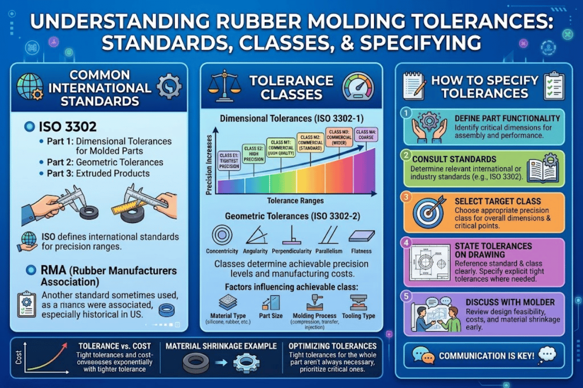
A Rubber molding tolerance describes the allowable variation in dimension that a molded rubber part may exhibit of its nominal dimension – and they behave nothing like the machined-metal tolerances most design engineers grew up with. At Meitu-Engelhardt, we see on average one drawing a week specifying a rubber gasket to 0.05 mm because the designer dropped a metal-part template. That tolerance is unachievable in compression molding, costly in injection, and nearly always unnecessary for the part’s true function. This document steps through the two standards that really rule the figures (RMA/ARPM and ISO 3302-1), the Fixed-versus-Closure break that silently determines your mold cost, the six shop-floor factors that blow tolerances out in the first place, and a decision structure for matching the tolerance class to the application without overpaying.
Quick Specs: Rubber Molding Tolerances
- Two standards: ARPM/RMA A1-A4 (US) and ISO 3302-1:2014 M1-M4 (international)
- Typical feasible range: 0.10 mm (A1, small parts) to 1.25 mm (A4, parts over 40 mm)
- General rule-of-thumb: rubber tolerances run ~4 wider than machined-metal tolerances for same nominal
- Two categories of dimension: Fixed (mold cavity-controlled) and Closure (parting-line-controlled, always looser)
- Most industry specifications: A3 (Commercial) – upgrade only the dimensions that matter
What Are Rubber Molding Tolerances (and Why They Differ From Metal)?
A rubber molding tolerance is the plus-minus band allowed on a nominal dimension of a molded rubber part. The band provides for the reality of processing a elastomer: rubber shrinks when cooled, takes in moisture, compresses when bolted down, and keeps changing dimension for hours after molding. Those effects do not happen with a machined steel in the same way, which is why a 0.025 mm callout routinely attainable for an aluminum braket after milling becomes impossible for an undulating 0.025” rubber gasket.
How do rubber tolerances differ from metal tolerances?
Three differences matter. First, rubber heats up then shrinks by 1.5-3.5% for cooling depending on the polymer – the shrinkage compensation is factored in to the cavity, not the part. Second, rubber is compressible, so any measurement under a gage foot is inherently a negotiation between the gage pressure and the durometer of the compound. Third, rubber takes in atmospheric moisture over time, so a part tested in-spec in the shop may seem slightly oversized when measured in a climate-controlled inspection office a month later. We see a 4 Rule: for the same nominal, an achievable molded-rubber tolerance is about four times larger than the machined-metal tolerance you would hold in your hand. 25 mm in aluminum to 0.05 mm is about 0.20 mm in a precision-molded elastomer – and that ratio is precisely what the ARPM and ISO tables codify into specified classes.
RMA / ARPM Tolerance Classes Explained: A1, A2, A3, A4
The North American reference is the Rubber Handbook published by the Association for Rubber Products Manufacturers (ARPM), formerly the Rubber Manufacturers Association (RMA). The handbook assigns four drawing classes for molded rubber dimensional tolerance: A1 high precision, A2 precision, A3 Commercial, and A4 Basic. Each class corresponds to a table of permissible variations that expands with the part size.
What is the tightest RMA rubber tolerance class?
A1 the tightest. It is limited to aerospace seals, medical-device elastomers and dynamic sealing geometries where really tight variation is needed. It takes costly precision-molds-machined, a lower number of cavities per tool (to keep cavity-to-cavity variation within the window), tight cure-cycle control and CMM grade inspection to hold A1. Based on the custom molded rubber parts we have manufactured at Meitu-Engelhardt, choosing A1 for the entire part would increase per-part component cost by between 40% and 60% relative to use of the default A3 with 2 or 3 A1 call-outs on critical features – which is nearly always the right choice.
The consolidated RMA table below shows Fixed (F) and Closure (C) dimensions in millimeters at five representative size bands. “Fixed” mean a dimension entirely between one mold halves; “Closure” is a dimension crossing the parting line (see next paragraph).
| Nominal Size (mm) | A1 F / C | A2 F / C | A3 F / C | A4 F / C |
|---|---|---|---|---|
| 0 – 10 | ±0.10 / ±0.13 | ±0.16 / ±0.20 | ±0.20 / ±0.32 | ±0.32 / ±0.80 |
| 10 – 16 | ±0.13 / ±0.16 | ±0.20 / ±0.25 | ±0.25 / ±0.40 | ±0.40 / ±0.90 |
| 16 – 25 | ±0.16 / ±0.20 | ±0.25 / ±0.32 | ±0.32 / ±0.50 | ±0.50 / ±1.00 |
| 25 – 40 | ±0.20 / ±0.25 | ±0.32 / ±0.40 | ±0.40 / ±0.63 | ±0.63 / ±1.12 |
| 40 – 63 | ±0.25 / ±0.32 | ±0.40 / ±0.50 | ±0.50 / ±0.80 | ±0.80 / ±1.25 |
Values compiled from the ARPM Rubber Handbook 8th Edition (RMA MO-1 designation tables). Over 160 mm, tolerance varies about linearly with size.
ISO 3302-1 Tolerance Classes: M1, M2, M3, M4 — The European Standard
Outside North America, the governing standard is ISO 3302-1:2014 — Rubber Tolerances for products, Part 1: Dimensional tolerances, published by the International Organization for Standardization. It defines four classes from M1 (fine) through M4 (coarse), again split by fixed and closure dimensions and binned by size. M1 (like ARPM A1) generally is nearly identical to the standard; M2 is near ARPM A2; et cetera. But the numbers are all slightly different, and begin to deviate at just over 100 mm (roughly).
Engineering Note: RMA A2 and ISO M2 tolerances are virtually equivalent for fixed dimensions under 40 mm. But once over 100 mm they can the range from 0-20% different, with ISO typically acting tighter at the coarse end and a little looser at the fine end. Never include the general standard on a drawing when dual sourcing large parts without calling it out specifically by part.
European automotive, medical and industrial purchasers will usually default to ISO 3302-1. North American aerospace, hydraulics and oil-and-gas specifications will usually default to ARPM/RMA. Global OEMs with double-sourcing requirements will often specify both on the same drawing (“Tolerances per ISO 3302-1 M2 / RMA A2”) enabling either supplier to go forward with a quote without a variance request.
Fixed vs Closure Dimensions: The Split That Decides Your Mold Cost
Both specifications split each dimension on a rubber part into two families. Learning that split is the single best thing a design engineer can do about rubber tolerancing because it remains hidden on most drawings and silently determines how much your mold costs.
| Dimension Type | Controlled By | Advantages | Limitations |
|---|---|---|---|
| Fixed (F) | A single cavity half — no parting line in the measurement path | Tightest band the process can hold; only influenced by shrinkage and tool wear | Limited to geometry features that live entirely inside one mold half |
| Closure (C) | Clamp force, flash thickness, parting-line wear — dimension crosses the split | Necessary for through-thickness and overall-height features | Always 25–60% looser than the Fixed band at the same class; gets worse as the mold ages |
The most common incoming-drawing error makes each of the worst problems we engineer for look very small. A closure dimension (typically a part thickness perpendicular to the parting line) gets specified as tight as a fixed dimension. Because closure is physically governed by how hard the press clamps and how thick the flash layer runs, tightening the closure number forces a switch to a much more rigid clamp system, a move from compression to transfer or injection molding, or a higher reject rate. Any of those routes doubles or triples the quoted unit price. Reassigning that one tight dimension from Closure to Fixed — simply by rotating the part in the cavity so the feature lives within a single mold half — preserves the original design intent and cuts tooling cost by a third.
Six Factors That Blow Out Rubber Tolerances on the Shop Floor
Those graphs show what can be pulled from the process. The actual shipped part depends on six shop-floor factors we every rubber molder sees each day. Parameters below are derived from the literature and the rubber industry; plant-to-plant variation will be significant.
- Polymer shrinkage (1.5-3.5%). Natural rubber and EPDM dominate at the low end; foamable silicone and fluoroelastomer are at the high end. mold cavities are machined oversized to account, but a core change mid-run — common when a customer reformulates for a new regulatory block — can move a complete size band out of spec until the tool is recut.
- Durometer variation (5 Shore A typical). A harder batch measures smaller using the gage foot and can read as undersize on dimensions using contact tooling. inspection specifications should specify gage type and load.
- Cure temperature and cycle time. Even a 2 C gradient can change crosslink density by 3-4 inch-reversal lock times.. Plants without active temperature control on the platens all drift appreciably between morning and afternoon shifts.
- Ambient humidity and temperature. rubber readilyabsorbes moisture over days to weeks. A part that ships at 25 mm OD will measure 25.1 mm two weeks later in a humid warehouse. Modern climate-controlled inspection rooms exist specifically for this reason.
- mold wear. Every shot moves a few micrograms of steel from the parting line; after 100,000 shots a tool that was just tight on an A2 closure dimension may now be loose on an A3. Tool-life planning should be integrated into the program schedule.
- Part features. Thin walls, deep features, unsupported spans, and high aspect ratios all tighten what the process can practically deliver by about a half a class. A simple O-ring cross section can hold A1 in silicone; a thin wall boot of the same compound can typically not.
One illustrative case: A (nominal) 25.0 mm OD EPDM gasket, run on a 16-cavity compression tool, drifted 0.3 mm from shift 1 to shift 3 on a summer Friday. The drift was actually due to a 4 °C swing in plant ambient temperature, not the cure platens – the uncured sheet was simply warmer going into the big mold in the afternoon. Parts which had been operating at the mid-range of the A3 band in the morning overshot the upper limit by noon. A portable AC box and a two hour sheet temperature soak brought the window back in.
“The number on the drawing is always the end of a story that started with the compound recipe, the mold condition, and the weather. Any conscientious rubber molder can hold A2 on pretty much anything on a good day — the real challenge is whether the plant can hold it on a bad day, across a full production run, on the dimension that actually matters.”
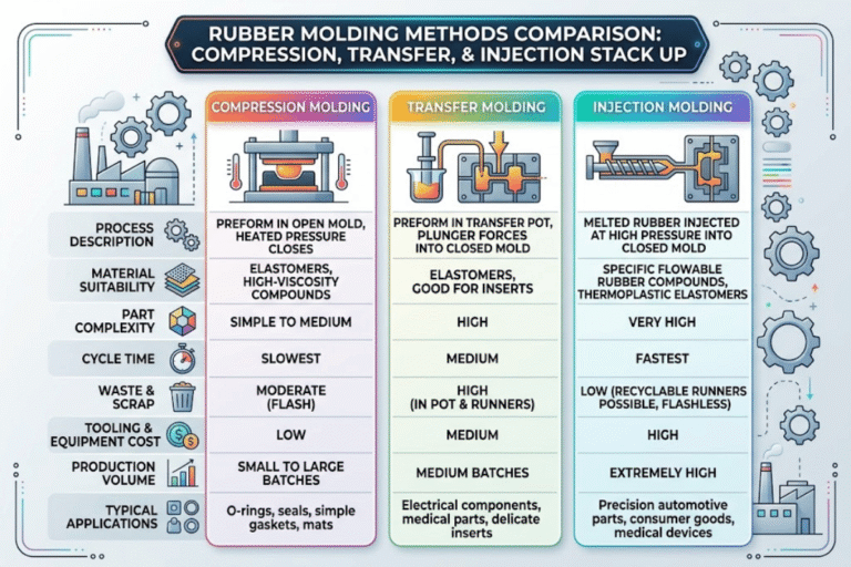
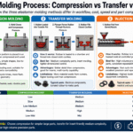
Compression vs Injection vs Transfer Molding: Which Process Holds Tighter?
Choose process type in conjunction with tolerance class with sustainable predictability. Compression molding is the oldest and cheapest process; it leaves flash, depends heavily on operator charge weight, and usually holds A3 as a default with A2 possible on simple fixed dimensions. Transfer molding adds a preform chamber and a plunger, which tightens closure dimensions considerably. Injection molding cures under full clamp with metered shots, delivers the best repeatability, and is the only process that routinely holds A1 across a production run.
| Process | Typical Tolerance Class | Cycle Time (rel.) | Tooling Cost Index |
|---|---|---|---|
| Compression | A3 default, A2 possible | 1.0× | 1.0× |
| Transfer | A2 default, A1 possible on fixed | 0.7× | 1.6× |
| Injection | A1 achievable, A2 routine | 0.5× | 2.4× |
Correct process choice is rarely “tightest tolerance wins” so. A high volume sealing ring, needing A1 on its inside diameter and A3 elsewhere, is a natural candidate for compression plus a precision-machined ID pin – way cheaper than an injection tool of similar cavitation. Cost difference only matters when A1 or A2 really is key across most of the part.
How to Specify Rubber Tolerances on a Drawing (Without Overpaying)

One can cost a lot by writing “general tolerance 0.05 mm” in the drawing title block, and then calling out a few features. Any fabricator seeing that note will assume the entire part must hold 0.05 mm, and price accordingly for A1 everywhere. Then again, the correct pattern is quite the opposite: specify a loose default class globally, tighten only the dimensions that need it.
The A3 default rule: unless there is a reason spelled out in the application, specify tolerances per ARPM A3 / ISO 3302-1 M3 – predefine this in the title block, unless otherwise stated. Next, separately call out with their own tighter callout (A2 or A1) the two or three dimensions that truly matter — critical sealing surfaces, mating diameters, key reference heights. In our production order book this pattern cuts quoted unit cost by 20-35% versus blanket A2 drawings, with no effect on functional yield.
Drawing Specification Checklist
- Explicitly state the standard used: ARPM A class; ISO 3302-1 M class; or both.
- Select a loose global default (A3 / M3 is almost automatically appropriate).
- Determine critical dimensions (most often only 2-4 per part) and set those to a tighter class with an on-piece callout.
- Separate fixed and closure dimensions on the drawing if any closure dimension is stiffer than A3.
- Define measurement: gage type, load, and temperature (for example, “measured at 23 ± 2 °C per ISO 23529 conditioning”)
- Indicate the compound family – A1 on silicone is not the same cost as A1 on fluoroelastomer
- Highlight dimensionsally temperature sensitive features (elastomer CTE is ~10 metal) if the end use runs hot or cold.
Tolerance Decision Framework: Match the Class to the Application
No one universal right answer – there is a right answer for a given application. Our framework below maps common rubber-part categories to the tolerance class that industry practice treats as appropriate. It is intended as a starting point for a quoting discussion, not a rule.
Which rubber tolerance class is standard for industrial gaskets?
For most static industrial gaskets and non-sealing bumpers, A3 (ARPM) or M3 (ISO) is the accepted and correct choice. Moving tighter only makes sense where the part is a dynamic seal, a precision medical component, or running in a mating tolerance stack that truly needs it.
| Application | Recommended Class | Why |
|---|---|---|
| Medical / aerospace dynamic seal | A1 / M1 | Failure consequence justifies precision tooling and inspection cost |
| O-ring groove seal, hydraulic / pneumatic | A2 / M2 | Leak path depends on squeeze % — tight ID/OD band matters |
| Static gasket, vibration damper, grommet | A3 / M3 | Function tolerates normal rubber size variation; cheapest rubber molding class that still fits |
| Bumper, mount, non-sealing cushion | A4 / M4 | Dimensional control is non-critical; lowest cost |
Frequently Asked Questions
How are rubber molding tolerances calculated?
View Answer
They are not calculated from first principles for each part – they are looked up from the ARPM or ISO 3302-1 table corresponding to the selected class and the nominal size band. That table already accounts for typical shrinkage, mold wear, and process capability. Only one calculation a designer does is choosing the correct size row and the correct column (Fixed or Closure).
What is the tightest standard rubber tolerance?
View Answer
ARPM A1 (0.10 mm on fixed dimensions 0-10 mm) and the equivalent ISO 3302-1 M1. Neither standard goes any tighter.
Why are rubber tolerances wider than metal tolerances?
View Answer
Three reasons stack: rubber shrinks 1.5-3.5% when it cools out of the mold (metal shrinks order of magnitude less); rubber is compressible so measurements vary based on gage pressure; rubber continues dimension-shifting for weeks as it absorbs atmospheric moisture. Typical observed size band ratio is about four to one – a rubber part contains about 4 the plus-minus band of a metal part at the same nominal dimension.
Does shrinkage get compensated in the mold?
View Answer
Yes – each rubber mold cavity is cut larger than the nominal part by the polymer’s known shrinkage factor. That compensation is specific to the compound; switching polymer mid-program usually requires a tool recut.
Can I specify tighter than RMA A1 or ISO M1?
View Answer
Technically yes, as a custom contract tolerance, but the cost curve becomes vertical. Parts tighter than A1 generally require single-cavity injection tooling, 100% CMM inspection, post-mold grinding operations, and a reject rate of 30% or more on the molding itself. Unless the application is a validated medical or aerospace program with documented failure consequence, the answer is almost always to redesign the mating feature in metal instead.
Need a second opinion on a rubber drawing before it goes out for quotes?
The Meitu-Engelhardt engineering team examines incoming customer drawings for tolerance class, Fixed/Closure designations, and mold-cost implications before any tool is cut. Most reviews identify one or two tight enable call-outs that reduce quoted unit cost 20-35% without compromising part function.
A note on the figures used in this guide: the RMA tolerance values listed are combined figures from the ARPM Rubber Handbook; they are the values most North American rubber molders quote from; and they agree with many published data. Actual attainable tolerances are a function of tooling and cavity layout, compound, cure cycle, and plant environment. This guide lists what can be routinely maintained across a full production run, not the absolute minimum for any particular part. Request a first-article inspection report for your particular geometry before qualifying a new tool.
References & Sources
- ISO 3302-1:2014 — Rubber — Tolerances for products — Part 1: Dimensional tolerances — International Organization for Standardization
- ARPM Rubber Handbook (RMA MO-1 designation tables) — Association for Rubber Products Manufacturers
- ASTM D3182 — Standard Practice for Rubber Materials, Equipment, and Procedures for Mixing Standard Compounds and Preparing Standard Vulcanized Sheets — ASTM International
- ISO 23529 — Rubber — General procedures for preparing and conditioning test pieces — International Organization for Standardization
- Engineering tolerance – Wikipedia
Related Articles
- Custom compression molded rubber parts and tooling
- Rubber injection molding for high-precision production
- Transfer molding process and tolerance capability
- EPDM rubber compound shrinkage and cure behavior
- Silicone molding tolerances for medical and aerospace seals
- First-article inspection for molded rubber parts