Get in Touch with Engelhardt

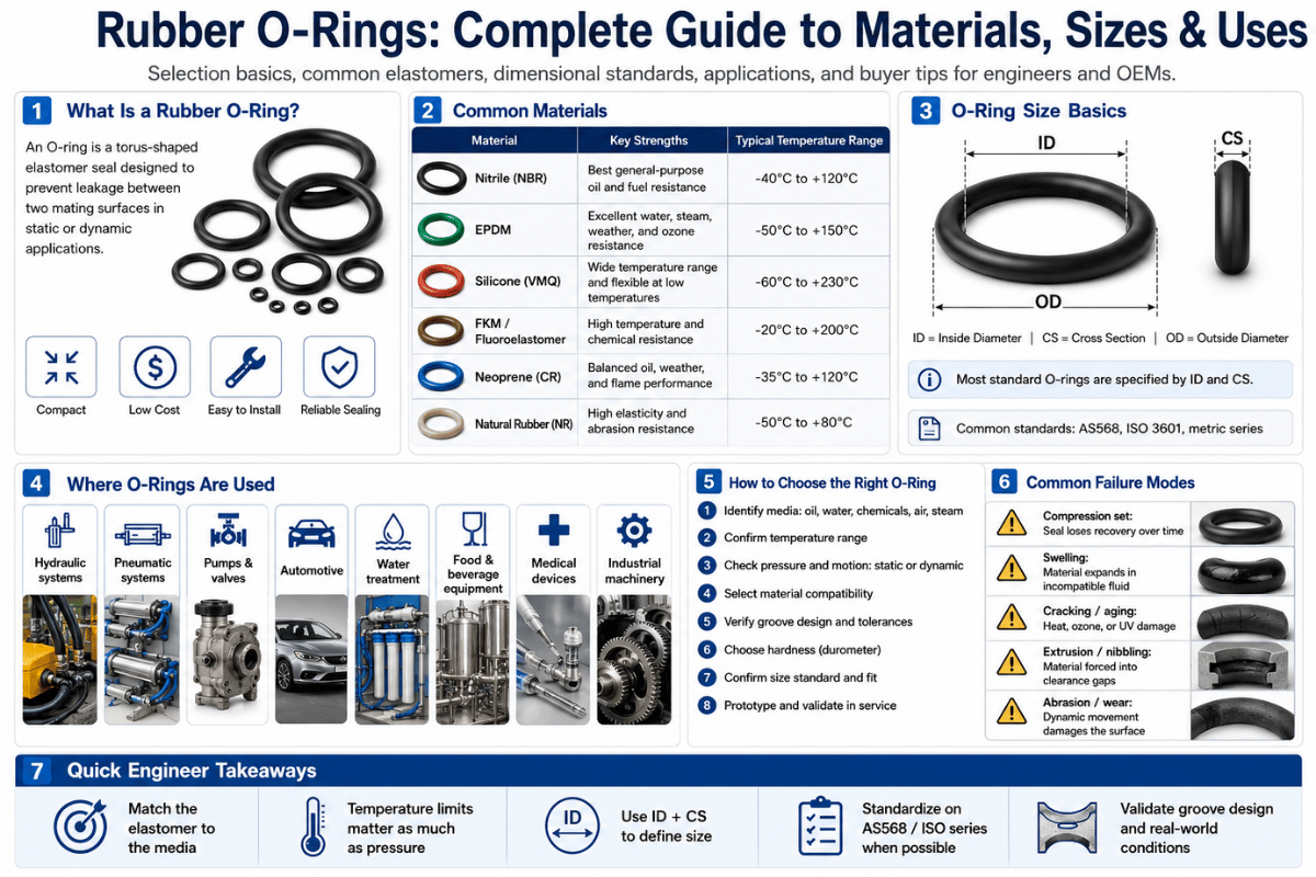
Rubber O-rings – the tiny round seals that maintain fluid and gas leakage within a hydraulic cylinder, a nut and a bolt, a jet engine or a satellite. In terms of the cost of the material, they are negligible but one decision in the design process that is wrong can result in a leak, loss of production, even a field failure more valuable than the part itself. This article describes what a rubber O-ring is and how it works, the materials used in its composition, the designation of an O-ring, failure modes, the differential failure frequency and how to go about selecting the right one without the marketing rhetoric.
Whether you are repairing a leak on a pump or designing O-rings into a new product, the same physics apply and the same five-letter list of elastomers is involved. You will have a proven selection technique to take away by the end.
Rubber O-Ring Quick Specs
| Cross-section shape | Circular (torus) — sealed by compression in a groove |
| Sizing systems | AS568 (imperial, SAE) · ISO 3601 (metric) — not interchangeable |
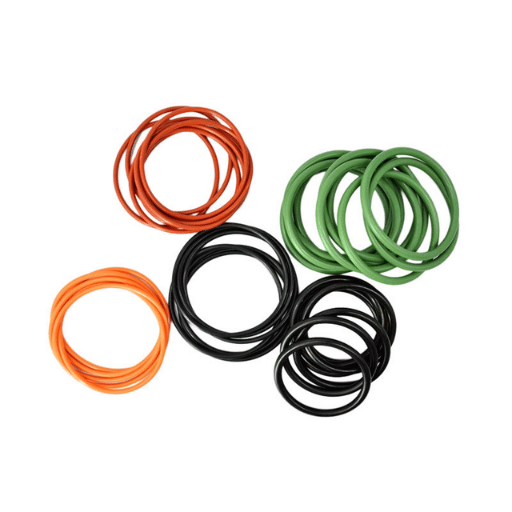
| Common materials | NBR (nitrile), FKM, EPDM, silicone, FFKM |
| Standard hardness | 70 Shore A (±5); 90 Shore A for high-pressure service |
| Temperature range | −65 °C to +316 °C across the material family |
| Application class | Static or dynamic (reciprocating, rotary, oscillating) |
What Is a Rubber O-Ring?
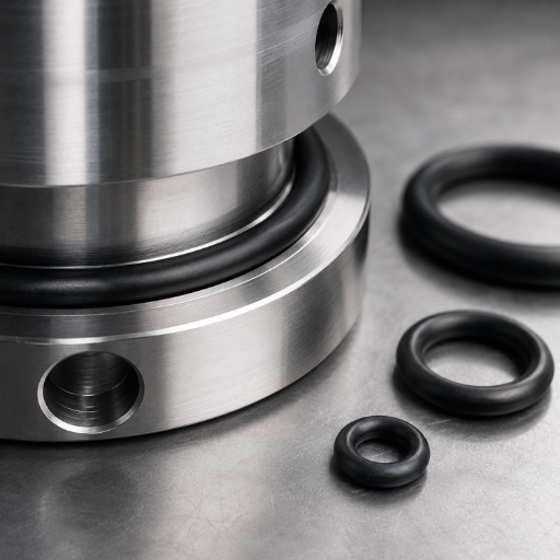
A rubber O-ring is a loop of elastomer with a round cross-section — a torus in geometrical terms. It is compressed into a machined groove between two mated parts so as to act as a seal—an elastomeric cross-section deforms to fill the gap, preventing the escape of a fluid or gas. Its name derives from that profile, not the ring shape.
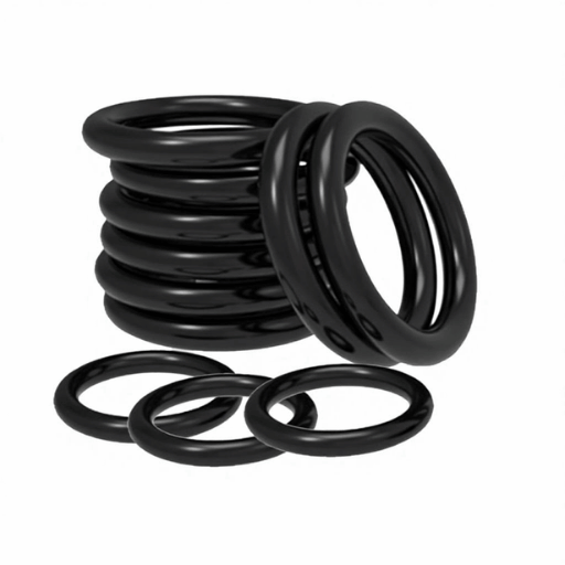
O-rings are the most common type of seal used in a mechanical design simply because they are cheap and simple and multiple use; the seal is bidirectional, pressure is sealed from either side. The use of O-rings can be found everywhere from a home kitchen faucet to the fuel system of a passenger car to segment joints of a solid rocket booster.
What Is the Difference Between an O-Ring and a Gasket?
Here’s the most usual point of confusion, and the simple truth is that an O-ring is a kind of gasket, but not all gaskets are O-rings. A gasket is any flexible piece that is placed in a joint to prevent leakage. Flat gaskets are just that, placed between two flat flanges that are held tightly together by bolts.
An O-ring is a specific mechanical gasket – it has a round hole, and nestles in a space, or groove, making use of system pressure to improve the seal (Explained below).
In practice: use a flat gasket for large, flat, bolted flanges; use an O-ring for grooved joints—particularly high-pressure or bidirectional seals. O-rings allow much higher pressures in a smaller envelope, than a comparable flat gasket. Dimensional and test conventions for moulded rubber rings are defined in standards such as ASTM D1414, the standard test methods for rubber O-rings.
💡 Key takeaway
An O-ring is a ring with a circular cross-section that fits into a groove. If you’ve got a joint with a machined groove section and you’re subjecting it to pressure then an O-ring is nearly always the place to start.
How Does an O-Ring Actually Seal?
There are two stages of an O-ring seal operation, and being aware of both steps is what makes the difference between a good and a bad design. Both stages rely on the sealing properties of the elastomer — its elastic deformation under pressure and its recovery afterward.
Step one- mechanical squeeze. When the groove is assembled, the O-ring is deformed (squeezed) between the bottom of the groove and the mating surface. This deformation — the squeeze — pushes the elastomer into contact with both surfaces and provides the first seal at zero pressure. Squeeze is expressed as a percentage of the cross-section diameter.
Stage two – pressure energization. Now comes the beautiful part of this system. As pressure builds, the incompressible O-ring is forced across the groove to the low-pressure side.
The elastomer swells into the annular space and exerts an increased force against the sealing surfaces. The O-ring is utilizing the pressure it is attempting to contain in order to create a better seal – the state engineers name self-energizing. This is the reason that the right-sized O-ring can hold thousands of psi where a loose flat gasket cannot.
How much squeeze you need is application dependent. Too little, the seal leaks; too much, and the elastomer takes a permanent set or extrudes into the gap. Typical design ranges are:
| Application | Typical squeeze | Surface finish (Ra) |
|---|---|---|
| Static face seal | 20–30% | 16–32 µin |
| Static radial (male/female) | 18–25% | 16–32 µin |
| Reciprocating (dynamic) | 10–20% | 8–16 µin |
| Rotary (dynamic) | 0–10% | 8–16 µin |
Observe the counterintuitive line: rotary seals get the least squeeze of all. Excessive squeeze in a rotating shaft will create heat by friction of the elastomeric material. Dynamic O-rings require more lubricated mating surface, not tighter squeeze.
📐 Engineering Note
Gland fill—ratio of O-ring volume to groove (gland) volume—should be about 60-85%. An elastomer is nearly incompressible and needs room to deform into. Gland shape which allows the O-ring to fill it too much results in a “trapped” seal that extrudes or balloons.
Groove sizing charts according to the AS568 cross section can be found in the standard (never freehand). Gland fill can have the opposite effect if the gland shape is a close fit: the shape will be prevented from deforming and the seal may be damaged.
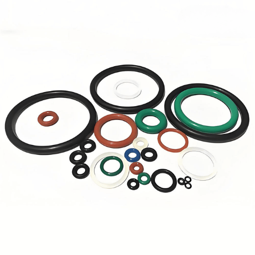
Rubber O-Ring Materials: NBR, FKM, EPDM, Silicone & FFKM
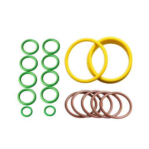
Material is the single most critical O-ring choice you will make. The same dimensions, machined in the wrong polymer, will leak, swell, harden, or crack within three to twelve weeks. For most industrial applications, just five elastomer families will be used and all of them are classified for heat and oil resistance according ASTM D2000 the line-callout standard for rubber materials.
| Material | Temp range (standard grade) | Strong against | Typical use |
|---|---|---|---|
| NBR (nitrile) | −40 to +125 °C | Petroleum oils, hydraulic fluid, fuel | Hydraulic and pneumatic systems, automotive |
| FKM (fluoroelastomer) | −25 to +230 °C | Heat, fuels, many chemicals, ozone | Chemical processing, aerospace, engines |
| EPDM | −40 to +135 °C | Water, steam, brake fluid, weathering | Plumbing, HVAC, outdoor equipment |
| Silicone (VMQ) | −65 to +205 °C | Extreme temperatures, dry heat | Food, medical, static high-temp seals |
| FFKM (perfluoroelastomer) | up to +316 °C | Almost every chemical and aggressive media | Semiconductor, harsh chemical service |
In addition to the five elastomers, the PTFE O-ring also finds use within narrow niches of chemical and high-temperature service, as rubber compounds are pushed to their extremities—albeit not with the elastic recovery of an elastomer. Nonetheless, whatever O-ring type one chooses, the ultimate consideration is matching the material’s chemical resistance to the media it will contact.
There are two material facts that deceive the designers. Firstly, silicone is not suitable for dynamic sealing even though its temperature figure is fairly high – as it has very low tensile strength and is very poor in abrasion resistance, it is best suited only for static applications. The second point is that FFKM is not only an improved version of FKM, it exhibits different thermal expansion characteristic and thus an FFKM O-ring may have its gland dimension recalculated, despite it appears the same dimensionally.
Cost varies very steeply with capability. NBR is the workhorse because it is ‘just right’ for most applications, FKM is a multiple of that, and FFKM can be a huge multiple of NBR. Choosing an exotic fluoroelastomer when nitrile rubber would do is one of the most common — and most costly — selection mistakes.
What Is the Difference Between Silicone and Rubber O-Rings?
Rubber is the general name – silicone is a type of rubber, in a list that goes nitrile, FKM, EPDM. When purchasers report a rubber O-ring, they are usually referring to a general-purpose nitrile(NBR) ring. Silicone rubber O-rings are a different animal – they hold up better under temperature variation and they are biologically inert (which is why they get used in food grade and medical equipment) but they are mechanically weaker. So the problem is not “silicone vs. rubber” but “which rubber”? And silicone tops the class whenever temperature ranges or inertness outweigh the strength requirements.
Temperature is not a footnote. The 1986 Space Shuttle Challenger disaster was caused by an O-ring that, in unusually cold weather near 36 °F at launch, lost resilience and could not spring back fast enough to follow the joint as it flexed. As NASA’s Rogers Commission Report made permanent, an O-ring material seals reliably only within its rated temperature range.
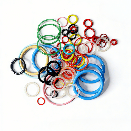
O-Ring Sizes and Standards: AS568, ISO 3601 & How to Measure
An O-ring is specified by two parameters: inside diameter (ID) and cross-section (CS). It is never specified by outside diameter. There are two global dimensional standards and mixing them up can be a practitioner shock.
SAE AS568 is the inch-based aerospace dimensional standard for O-rings. It assigns each size a dash number — a -012 or -214, for example — and covers inside diameters from roughly 0.029″ up to 26″. ISO 3601 is the metric O-ring standard, published in several parts covering dimensions, housings, quality, and anti-extrusion design.
Here is the trap: since SAE AS568 and ISO 3601 use different measurement systems with different nomenclature, an AS568 dash number means nothing in the ISO system. Order a “-214” without naming the standard and you can receive a ring that will not seat in your gland. Always state both the standard and the size.
📐 Engineering Note — How to measure an O-ring
To measure an O-ring, measure the relaxed ring with a pair of diameter gauges and a cross-sectional gauge or a micrometer and record the average of about five samples. Measuring the ring stretched is not recommended – elastomers tend to deform isotropically, shrinking in apparent CS and inflating in apparent diameter when tensioned, giving a false-sized reading. Unknown rings, measure often and average.
That spread is a point professionals stress when buyers tighten tolerances on flexible parts too far:
“Specifying ±0.001 on dimensions is unrealistic for most fabrication processes for a flexible seal — your spec is for the mold, not the part.”
Standard O-rings are generally supplied at 70 Shore A hardness with a ±5 tolerance. For repair and maintenance work, handy O-ring kits pre-sort the most common sizes into a convenient box, saving time on dimensioning. When your size is nonstandard, custom tooling can be made to give whatever ID and CS the application needs.
Static vs. Dynamic O-Ring Applications
Label the application as static or dynamic before selecting an O-ring – it affects the design of the squeeze, the surface texture, the hardness of the material, and the type of lubrication. That static-versus-dynamic split is the major division in sealing design after material selection.
A static seal involves no relative motion between the mating surface – a bolted cover, a threaded port, a pipe flange. While in dynamic seal involves motion:- a reciprocating piston in a hydraulic cylinder, a rotating shaft, or an oscillating valve stem.
✔ Static applications
- Higher squeeze tolerated (20–30%)
- Surface finish Ra 16–32 µin is adequate
- Minimal lubrication needed
- More forgiving of material choice, including silicone
⚠ Dynamic applications
- Lower squeeze (reciprocating 10–20%, rotary 0–10%)
- Smoother surfaces required (Ra 8–16 µin)
- Continuous lubrication is mandatory
- Needs abrasion-resistant compounds — not silicone
Dynamic service is unforgiving because every cycle wears the seal. A reciprocating O-ring in a pneumatic actuator can see millions of strokes; a rotary O-ring on a shaft fights friction heat the whole time it runs. Get the surface finish wrong- too rough and it abrades the ring, too smooth (mirror-polished) and it cannot hold a lubricant film -and a dynamic seal fails early regardless of material.
💡 Key takeaway
Decide static or dynamic first. Everything downstream – squeeze, finish, hardness, lubrication – is set by that single classification.
Common O-Ring Failure Modes and How to Spot Them
A failed O-ring is a diagnostic record. Its appearance tells you the root cause- and replacing it with an identical ring without reading that record guarantees a repeat failure. Most failures trace to one of three forces: incompatible media, temperature outside the rated range, or mechanical stress the seal was never designed to absorb. Here are the failure modes engineers see most, and the visual signature of each.
- Compression set- the ring is permanently flattened on two sides and will not spring back. Caused by over-compression, excess heat, or a material with poor recovery. One of the most frequently cited O-ring failures.
- Extrusion and nibbling- chipped, ragged edges on the low-pressure side, where the ring was forced into the clearance gap. Caused by high pressure plus too large a gap; the fix is a harder compound or an anti-extrusion backup ring.
- Explosive decompression- internal blisters, splits, or pitting after a rapid pressure drop. Gas absorbed into the elastomer expands faster than it can escape. Critical in hydrogen, CO₂, and high-pressure gas service.
- Thermal degradation- radial surface cracks and a hardened, shiny skin. Here the material was run above its temperature range.
- Chemical swell or degradation- softening, blistering, or a measurable change in size and hardness. Here the elastomer is incompatible with the media — a chemical-compatibility miss.
- Abrasion- a flat worn band with fine parallel scratches, on one side only. A dynamic-seal problem from rough surfaces or lost lubrication.
- Spiral failure- a circumferential spiral cut around the ring. Here the seal twisted instead of sliding during slow reciprocating motion.
- Installation damage- clean cuts or nicks. Here the ring met a sharp groove edge or thread during assembly, often because it went in dry.
Will an O-Ring Stop a Leak?
Yes – provided the elastomer is right, the size is correct, and the seal is correctly installed in a suitable groove. An O-ring cannot prevent a leak with a scratched sealing surface, or a corroded or worn groove, or an elastomer that has already taken a compression set, or the wrong gasket material for the process fluid or gas. It’s often the case that the worst offenders for O-ring failures are not the rings, but the mating surfaces. A leak that returns immediately after an O-ring change is usually a damaged mating surface, not a bad ring — inspect the groove and the shaft before blaming the seal.
⚠️ Common mistake
Throwing a failed ring away without investigating it is the most costly habit in O-ring maintenance. A maintenance team on a hydraulic press kept repeatedly installing identical nitrile rings, which exhibited clear extrusion damage every single time. Root cause: a worn rod-gland clearance, obvious from a single inspection of the failed ring. It took months of repeated repairs before the cause was found.
How to Select the Right Rubber O-Ring: The PETS Check
O-ring selection seems overwhelming to newcomers because there are hundreds of different compounds listed in catalogs. In practice the decision process is quick — there are four questions that it pays to answer in order, using our concept of the PETS check – Pressure, Environment, Temperature and Size/movement.
The PETS Check — four questions to a full O-ring spec
- P – Pressure. How high is it, and is it constant or cyclical? Low pressure: use a standard 70 Shore A. High pressure: go for 90 Shore A and/or an anti-extrusion backup ring.
- E – Environment. Which fluid or gas will be in contact with the seal? This is best checked by putting the elastomer in a chemical-compatibility chart – this is the most important consideration after pressure.
- T – Temperature. What is the minimum and maximum operating temperature? (And transients too!) Seal the limits, not the middle.
- S – Size & movement. Is it a static or dynamic seal in AS568 or ISO 3601 sizes? Movement will influence the squeeze, the finish, and the hardness.
To use these four questions most OEMs find their choice of elastomer is rather predictable – below is a table showing the results using typical operating conditions to determine an ideal starting material, followed by an illustration of how this can be refined.
| Service condition | Starting material | Why |
|---|---|---|
| Hydraulic oil, ≤100 °C | NBR (nitrile) | Right-sized, lowest cost, excellent oil resistance |
| Hot fuel or chemicals, to 200 °C | FKM | Broad chemical and heat resistance |
| Water, steam, brake fluid | EPDM | Resists water and polar fluids; never use with petroleum oil |
| Food, medical, static high heat | Silicone | Inert and temperature-tolerant; static service only |
| Aggressive chemicals, extreme heat | FFKM | Near-universal resistance; specify only when justified by cost |
One example illustrates the importance of following the order of the decision criteria. An engineering team specified an EPDM O-ring to be fitted to a small-gearbox enclosure because it was said that “EPDM is resistant to weather”. Within a month the seals had swollen and gone soft: the fact was that the gearbox was lubricated with petroleum oil, which EPDM cannot resist. Had they applied the PETS order to the specifications they would have spotted this potential problem immediately. The pressure and environment parameters are applied first, all wrong materials eliminated, then temperature and size reduce the possibles to the final choice.
How Rubber O-Rings Are Made: Molding Processes
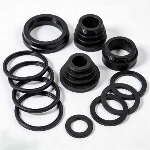
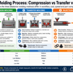
O-rings are molded by curing (vulcanization) of an uncured elastomer in a heated mold. Three primary processes are used, and selection depends on tooling cost, production volume and accuracy requirements.
- Compression molding – uncured rubber is charged directly into the space, and then compressed. Minimum tooling costs; suitable for low-volume production and large cross-sections. Will require flash trimming.
- Transfer molding – uncured rubber compound is moved from a pot under heat through sprues in a heated cavity into the mold blocks. Higher tooling costs but greater dimensional control than compression molding.
- Injection molding – the rubber is heated and injected directly into a closed mold. Tooling investment is very high here, but so are the accuracy and production volume.
Two manufacturing realities are relevant to the purchaser. Quality of cure cannot be seen but is critical: an undercured O-ring appears identical but performs poorly in compression-set resistance and fails prematurely in service. An off-the-shelf AS568 o-ring will satisfy most uses; choosing more elaborate or custom tooling is only meaningful if the groove is not standard, a specific compound required, or high production volumes make injection molding economical.
Across all three processes, the canonical reference for groove and material design is still the Parker Hannifin O-Ring Handbook (ORD 5700).
A rubber manufacturer that blends its own compounds monitors the cure recipe and material certification from start to finish. Engelhardt runs nine in-house elastomer compounds and all three molding processes under one roof — see its custom rubber O-ring molding capabilities for non-standard sizes and specialty compounds.
The Rubber O-Ring Outlook: What’s Changing in 2026
O-ring technology is mature, but three forces are reshaping material selection right now, and each one has a direct impact on procurement.
PFAS regulation and fluoroelastomers. FKM and FFKM are fluoroelastomers, a class caught up in the EU’s sweeping PFAS restriction proposal. Timing is concrete: the European Chemicals Agency’s risk assessment committee opinion is due in 2026, with a socioeconomic opinion and any phased-in industrial restrictions to follow toward the end of the decade.
Important: this is a groundwork phase, not a ban – EU trade associations are actively lobbying for exemptions to cover key sealing uses, and those exemptions are widely expected to be granted. If you’re planning next-generation products over multiple years, sit in on the ECHA PFAS process, but don’t panic-requalify in-use FKM seals in 2026.
Hydrogen energy. Expanding hydrogen fuel and storage is raising demand for O-rings that resist explosive decompression. Because the hydrogen molecule is so small, it diffuses readily into elastomers, so hydrogen-service seals increasingly call for specially formulated FKM and FFKM compounds rather than standard grades.
Electric vehicles. EV battery and thermal-management systems need many seals, but they also create competition: liquid-applied sealants are displacing some discrete O-rings in battery-pack joints. Where O-rings remain, the trend is toward higher-temperature compounds suited to fast-charging heat.
The practical advice for 2026: continue to specify nitrile rubber where it fits — PFAS rules have no bearing on it, and it remains the most cost-effective seal — and reserve fluoroelastomer requalification effort for genuinely PFAS-exposed product lines.
Frequently Asked Questions
What are the two main types of O-rings?
View Answer
By function, there are static and dynamic applications. In a static application, the mating surfaces of the components are stationary. In a dynamic application, the mating surfaces are moving back-and-forth, rotating or oscillating.
This organization determines the squeeze, surface finish and material, long before selecting a size.
What is the purpose of an O-ring?
View Answer
O-ring: To seal a fluid or gas from passing between two parts of a mechanical joint. It is normally placed in a groove and compressed between two parts, then deforms to fill the gap — and as system pressure rises, it seals tighter as the load increases.
How do I identify an unknown O-ring’s material?
View Answer
Elastomer selection is not trivial: color alone can be black NBR, FKM, or EPDM. Use context as the first guide: petroleum oil indicates nitrile, water or brake fluid means EPDM, high temperature points to FKM or silicone. For clarification and guarantee of material, analyze a sample, do not guess.
Can a rubber O-ring be reused?
View Answer
Not usually. After using the OE O-ring, it has already experienced some compression set, and immediate reinstallation can cause a failure and leak. When high costs are not involved, it is normal to change the O-rings at each service interval.
Are rubber O-rings still used in modern engineering?
View Answer
Absolutely. O-rings are the default seal in all forms of hydraulics, since automotive and aerospace uses, and process equipment. Liquid sealants are gaining some traction in high-value applications like EV battery packs, but in general the O-ring’s versatility and low cost rules the day.
What lubricant should be used on O-rings?
View Answer
Select a lubricant compatible with both the elastomer and media – silicone greases are usually applicable, but check on hardness, media compatibility, and media temperature for each use case. Lubricate the seal for installation and dynamic operation, and verify media compatibility.
How much pressure can a rubber O-ring hold?
View Answer
A correctly designed O-ring seals into the thousands of psi. What limits it is not the elastomer but the clearance gap: as pressure rises, the ring tries to extrude into that space. High-pressure designs use stiff 90 Shore A compounds and anti-extrusion backing rings.
Need a specific O-ring size outside the regular catalog – special compound, diameters, or dimension…?
About This O-Ring Guide
This guide combines O-ring material, size, and failure data from preexisting standards (SAE AS568, ISO 3601, ASTM D2000 and D1414) and the knowledge of the Engelhardt silicone and rubber engineering team, which has manufactured custom molded O-rings and elastomer seals since 2009. Design ranges such as squeeze percentages and surface roughness are typical values – check the gland and material specs for the particular media and seal before production.
References & Sources
- SAE AS568 — Aerospace Size Standard for O-Rings — SAE International
- ISO 3601-1 — Fluid power systems, O-rings: inside diameters, cross-sections, tolerances — International Organization for Standardization
- ASTM D2000 — Standard Classification System for Rubber Products in Automotive Applications — ASTM International
- ASTM D1414 — Standard Test Methods for Rubber O-Rings — ASTM International
- Report of the Presidential Commission on the Space Shuttle Challenger Accident – NASA
- Per- and polyfluoroalkyl substances (PFAS) — restriction process — European Chemicals Agency
Related Resources
- Custom Rubber & Silicone O-Rings — non-standard sizes and specialty elastomer compounds
- Rubber Compression Molding – process for best-for-ductility compositions, bulk production
- Rubber Injection Molding – high-precision, high-volume production
- Rubber Transfer Molding – moderate-cost alternative with less dimensional variability
- Custom Rubber Molding Capabilities — full elastomer manufacturing overview